
Dicontinued -WiFi Bot Control – Using NodeMCU (ESP8266)
 WiFi Bot Control was built back before the ESP8266 came out, so WiFi options were limited and the ability to directly stream data over WiFi to the same MCU that controls a robot was next to impossible. That changed with the intro of the ESP8266. I’m going to show you how to streamline WiFi Bot Control and remove the need for a separate webserver. We’ll also look at options to streamline the IP camera connection. Note – if this is the first time you are looking at WiFi Bot Control, there is important information, features & instructions on the original posting.
First a few important notes:
- The best part about this solution is that it removes the need for you to have a separate webserver to accept the data. This is a huge improvement to WiFi Bot Control as it removes a significant barrier.
- This is not a turnkey solution. You have to do a bit of work and need some experience with Arduino/coding. That said, getting WiFi Bot Control running is not rocket science.
- This write-up focuses on showing how to connect WiFi Bot Control via your local wifi network to a NodeMCU and see the joystick values stream. It also has a sample motor driving routine. You should expect to have to tweak the exact motor power routines. You can also look at the original WiFiBotControl sketch to use other bits.
- I am using the NodeMCU Mini v1.0 (ESP8266) MCU. This is now my go-to WiFi MCU. Love this thing. That said, this should work for any other WiFi-enabled MCU (i.e. WeMo, Arduino mkr1000, Adafruit Huzzah, NodeMCU etc etc). You may need to do some tweaking of pins etc.
- Note that most of the FAQ and other notes on my original write-up(WiFi Bot Control page) still apply. Use that as a source to understand how it works and it’s features. Just ignore the parts related to the Server Components & Setup bits.
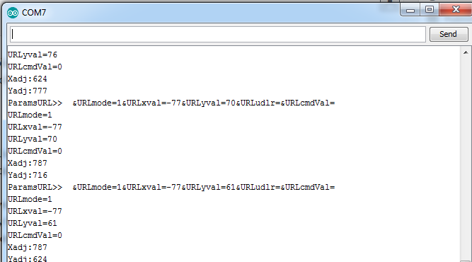
- Important!!! About WiFi Bot Control. You will notice 2 versions on Google Play. One is free, the other is paid. Their functions are identical, so you can start with the free version. The only difference is the free version sends 0’s for x and y, and other generic data, while the paid version will send the actual reading from the joystick. That’s ok as all you need to confirm is that the NodeMCU is getting the command stream parameters. I have Serial.print’s in the code that shows this, so when you see it, you know the Pro version will work. It will look like the following. In your case, the values will all be “0”.
Before you start, note that we are not going to worry about hooking up motors, motor drivers or LEDs yet as that will just complicate things. The focus here is getting WiFi Bot Control connected to your MCU over your local WiFi network. The rest is up to you.

Connecting WiFi Bot Control app to your MCU:
Note: WiFiBot Control is no longer available or supported. There are other options that can serve a similar purpose. Have a look at Blynk. Thanks for those that supported in the past.
- Download WiFi Bot Control from Google Play and install it.
- Download the WiFi Bot Control Arduino source (below). You will need to make sure you have the NodeMCU v1.0 (or whatever wifi capable board you have) drivers installed. To see how to set these up in the IDE, Google is your friend. Just search “setting up NodeMCU on Arduino”.
- Once you’ve got your Arduino environment setup, try a test sketch on the NodeMCU just to ensure it can connect to your home network. Get that working before moving on.
- Open the WiFi Bot Control demo sketch and set the WiFi SSID and password to the one from your network.
- Open the Serial window, upload the sketch, get a beer then watch the console. You should see it connect to the network and get an IP address. Take note of that address.
- If compiling the sketch didn’t work, well, you’re SOL.. Ok not really, it’s probably some setup step you missed. Again, the purpose of this post is not Arduino 101 (sorry) :-). Run through your setup steps again to get that working so it compiles. This sketch only uses ESP8266-related libraries, so it should work. Move on once you get the sketch to compile.
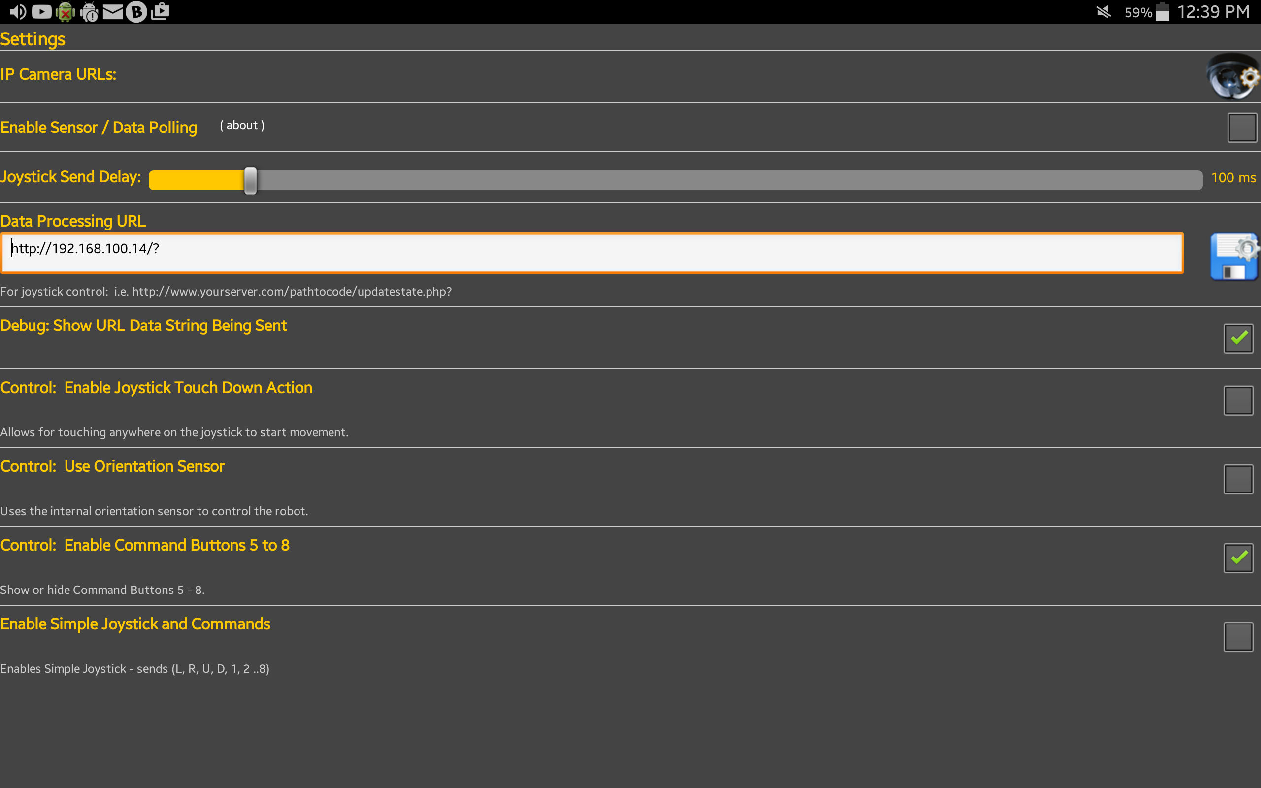
- On your Android device open WiFi Bot Control, go to the settings page by clicking the gears (top right). The below window will open.
- In the Data Processing URL field, enter in the IP address of your NodeMCU (noted in step #6). It needs to be in the format as shown in the below image. http://[yourIPAddress]/? In my case http://192.168.100.14/?
- Click the save icon, and go back to the main screen.
- Now, move the joystick and you should see the values for your parameters streaming through the Serial console when you move the joystick or click command buttons.
- If it doesn’t work, you need to make sure your Android tablet is connected to the same network as the NodeMCU. If you are still having issues, check the FAQ on the original WiFi Bot Control page. If you are getting results, congrats, you can now make your robot move! The sample code below has some baseline functions for you to start this with. Note that the type of motor driver you select will dictate different code changes. More on that below.
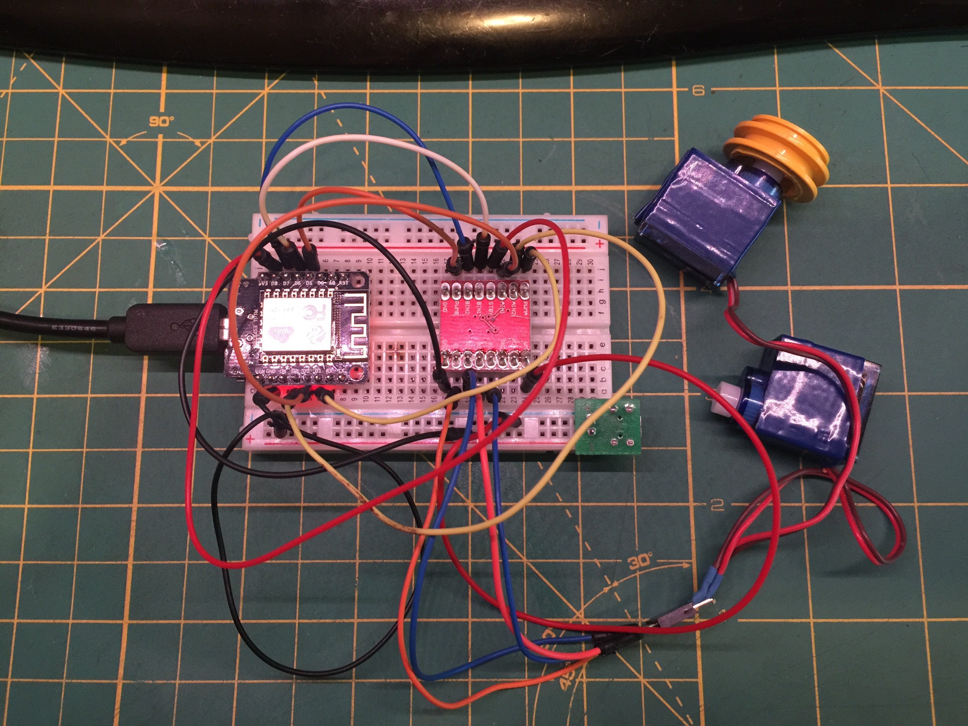
Motor Driver & Motors:
There are lots of options out there to drive motors. You can use standard DC motors, servos, stepper motors etc. The purpose of this post is not to educate in that area. There are plenty of resources out there. The original WiFi Bot Control used the Digispark Motor controller, so there is lots of info and sketch details there on how those motors were driven. For this example, I am using a dual h-bridge controller. There are many out there like this from Sparkfun, or this.
For each motor:
- 1 pin is used to set the speed via PWM.
- 2 pins are used to set direction.
- Full details and explanation here.
** Note: I am going to be working on a version that does not use a motor controller, but instead motors directly connected to the MCU with the Servo library. This should simplify things even more.
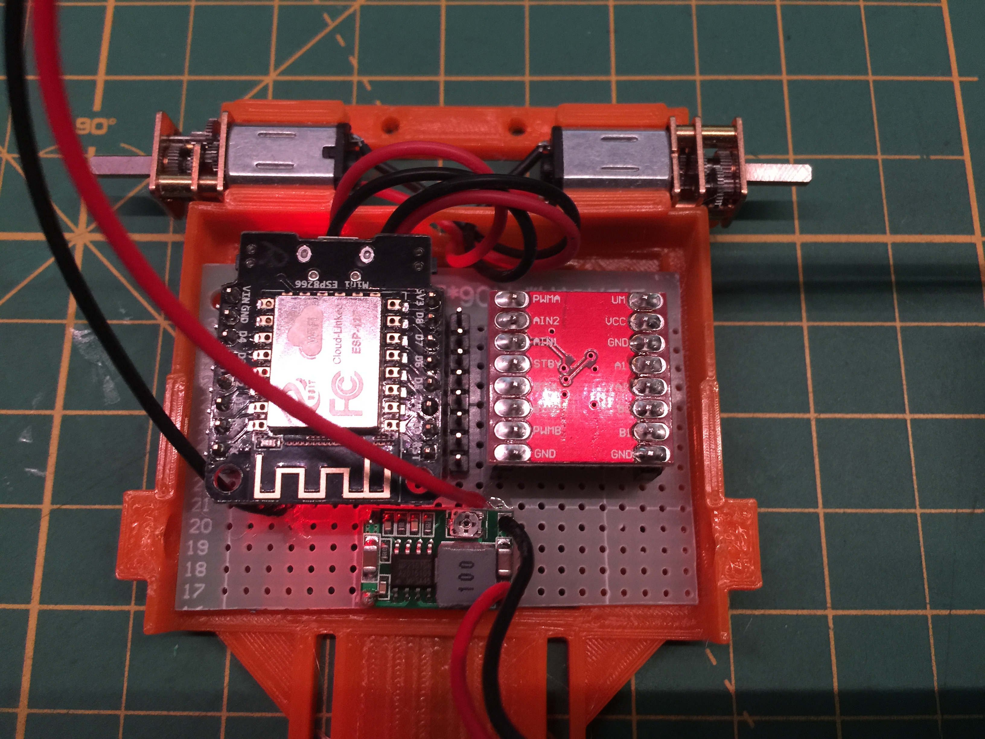
For the sample sketch I provided, connect the pins as follows. Note this is for a NodeMCU Mini. It may differ if you have another board:
| Motor Driver | NodeMCU (Mini) |
| PWMA | D1 (GPIO5) |
| AIN2 | D3 (GPIO0) |
| AIN1 | D2 (GPIO4) |
| STBY | D8 (GPIO15) |
| BIN1 | D6 (GPIO12) |
| BIN2 | D7 (GPIO13) |
| PWMB | D5 (GPIO14) |
| VM | VCC (5V) |
| A1 | Motor A + |
| A2 | Motor A – |
| B2 | Motor B + |
| B1 | Motor B – |
| GND | GND |
Connecting your IP Cam:
Refer to the IP Cam configuration on the original WiFi Bot Control page (link at top of page)
The Sketch: WiFiBotControlNodeMCUDemo
Important: Because it’s always confusing figuring out which motors are connected to which output, you may have to play around with the below configuration values to get them to spin the right way. Easy way to test is to plug it all in, then drive the joystick straight fwd (large Y value). The first part below should set both motors fwd. If not, change the last value from 1 to 0. Or, reverse the motor connectors. Once you have this figured out, it will fix the reverse option. Then test left. If it does not go the right way, flip the first value (2 or 1).
//now determine fwd or back as this will result in flipping values.
if (yVal >= 0) //going forward
{
move(2, leftSpeed, 1); //motor 1, full speed, left //was note ESP PWM resolution is 0 > 1023
move(1, rightSpeed, 1); //motor 2, full speed, left //was 255
}
else //reversing
{
move(1, leftSpeed, 0); //motor 1, full speed, left //was 255
move(2, rightSpeed, 0); //motor 2, full speed, left //was 255
}
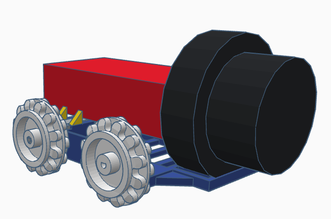
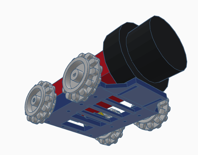
WiFi Bot
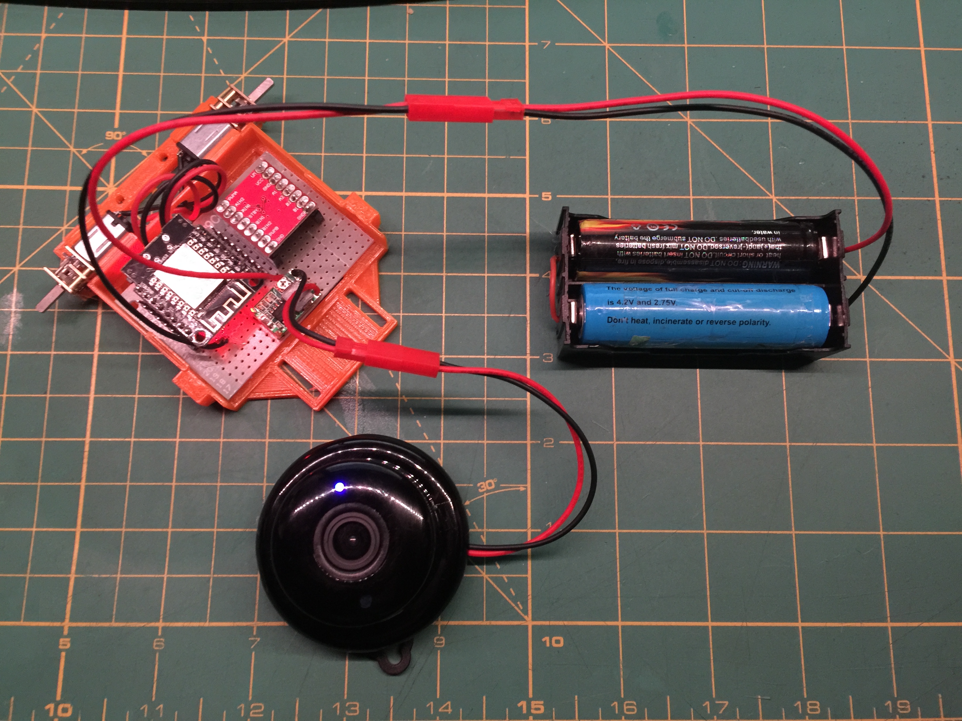
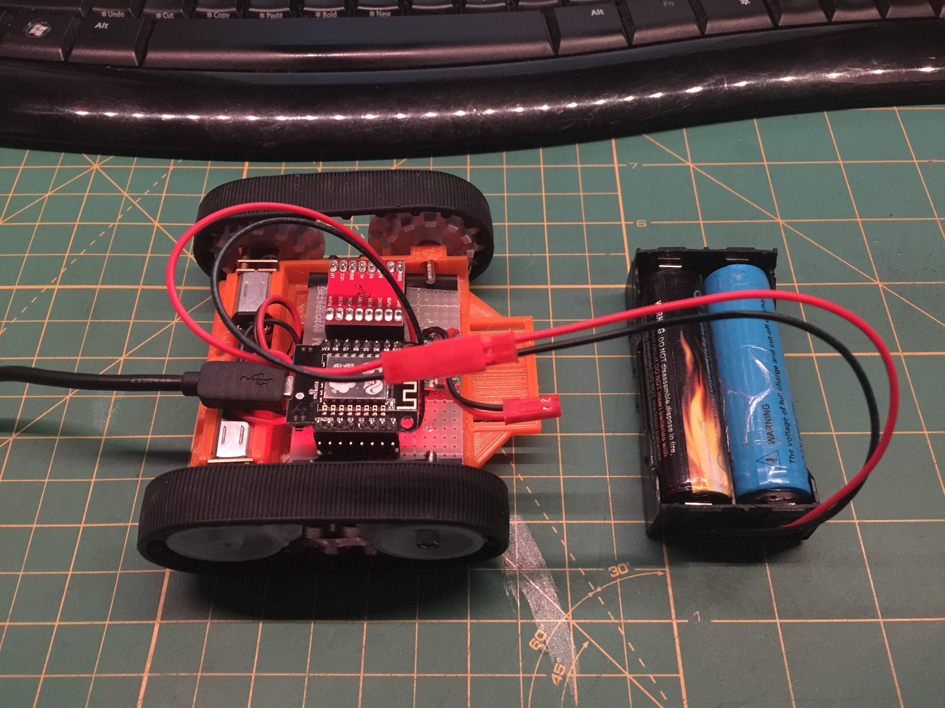
Here’s a bot I’m modelling to print up in the coming weeks. I’ll be using a WiFi Bot Control, NodeMCU, a motor driver, 2x 18650 batteries in series and a Digoo IP Camera. I’m expecting the camera to be a bit of a pain as they (currently) have no web interface and the camera is not accessible via http. Yes. in 2017…


wifi bot control pro is not available play store.
That’s correct – as noted in the pages. I’ve updated the text to make it more clear and noticeable. Thanks.
So how can someone get the app? I need it!
Hi. As indicated in the posting, it’s been discontinued. Thanks for your interest. I suggest you check out Blynk.cc.