
Basement Disco: NeoPixel Music Sync with MSGEQ7
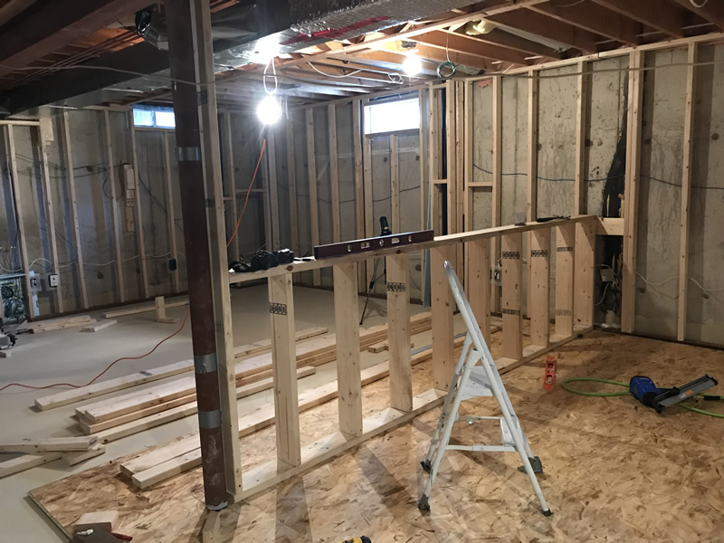
I didn’t have a lot of time in 2019 for projects as much of it was dedicated to finishing the basement. A year ago it was nothing more than concrete, storage and dustballs. Took the job on myself and did everything except hanging drywall and mudding (I hate that part). Best part of doing your own basement is you get to hack in all the bits and pieces necessary for future projects – like LED lighting & Nextion displays, Blynk etc. Also built my own man-cave to house all my electronics stuff, 3D printer, laser engraver and a custom-built fume extractor to vent the nasty stuff. But! That’s not what this is all about….
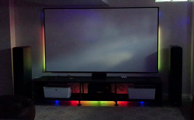
This post is about marrying love of music with lighting – namely NeoPixel LED strips installed behind my projector screen. The first revision was to add mood lighting behind the screen during movies / entertaining. This used a variety of readily-available NeoPixel themes all tied into Blynk to allow control from my phone. Not being satisfied with status-quo, I wanted the strips to interact with the music to add entertainment value – a party mode of sorts. I wanted a little Saturday Night Fever flavor but be able to gracefully have it hidden from plain sight until needed. After recently adding a set of Nanoleaf light panels to the basement, I turned my focus to figuring out what I could do with the NeoPixel strips I had mounted around the projector screen as well as under the audio cabinet.
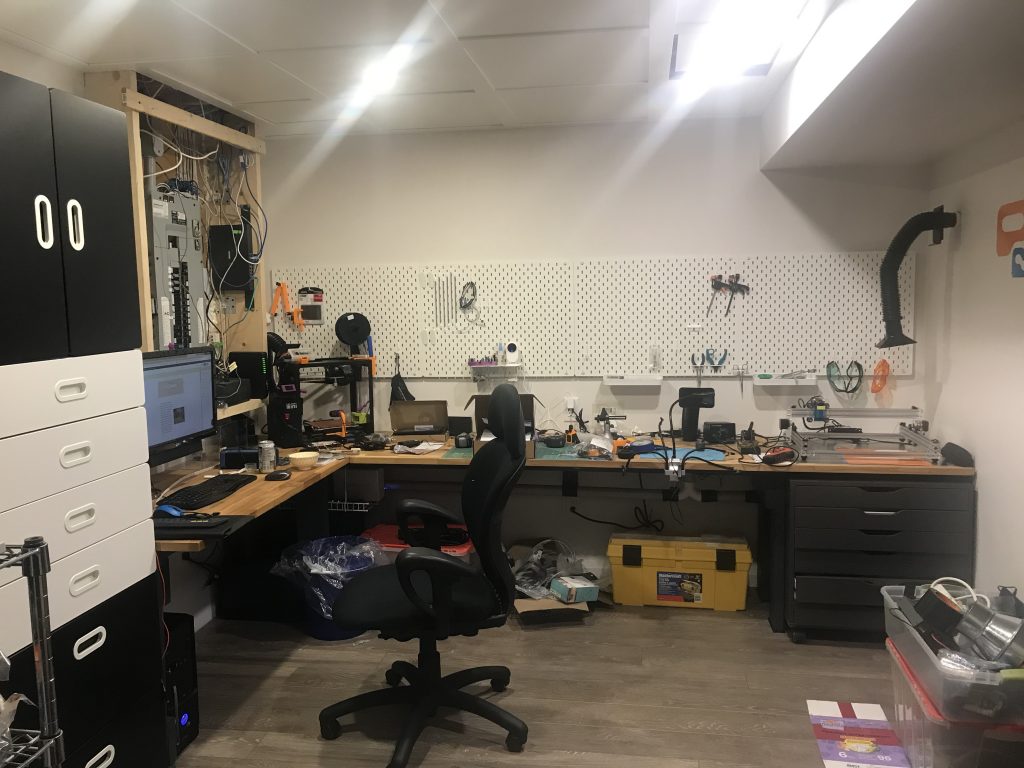
The Workshop 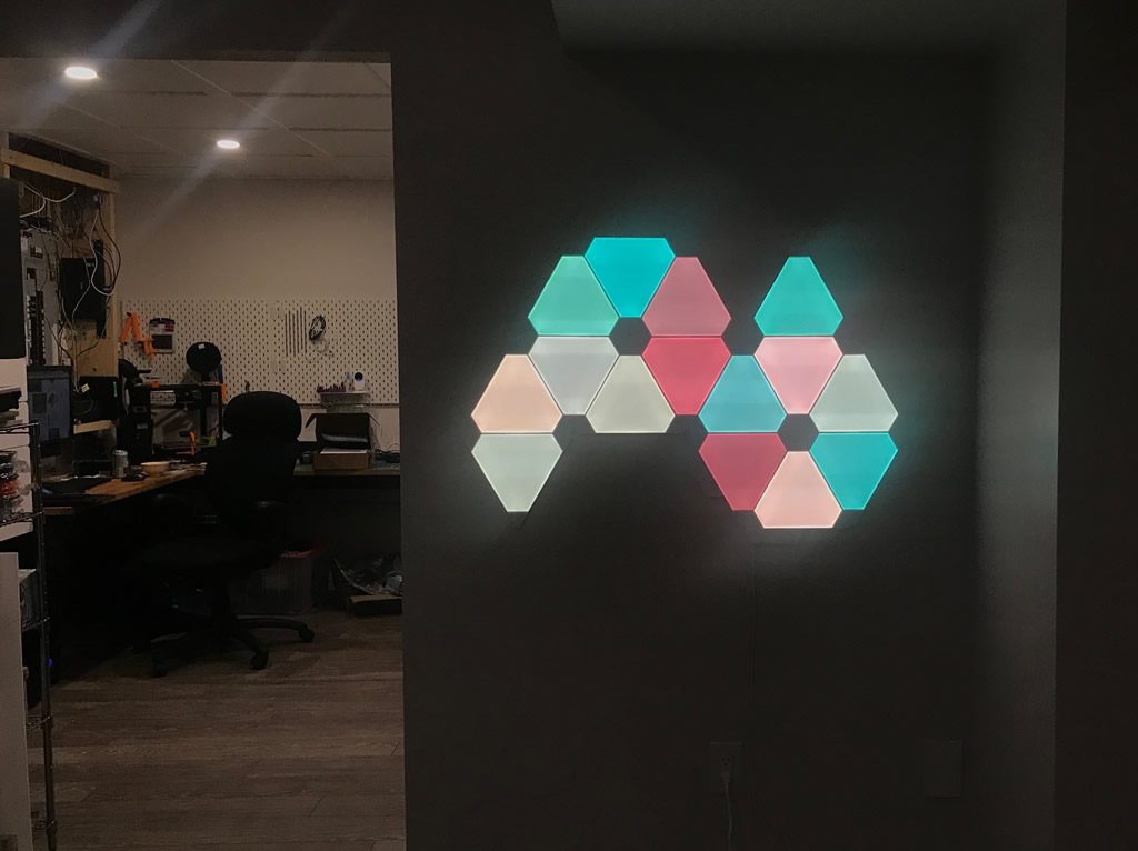
NanoLeaf Canvas 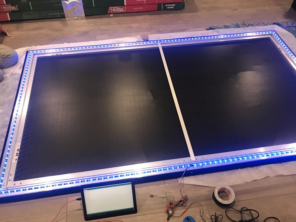
Mounting the NeoPixel Strip 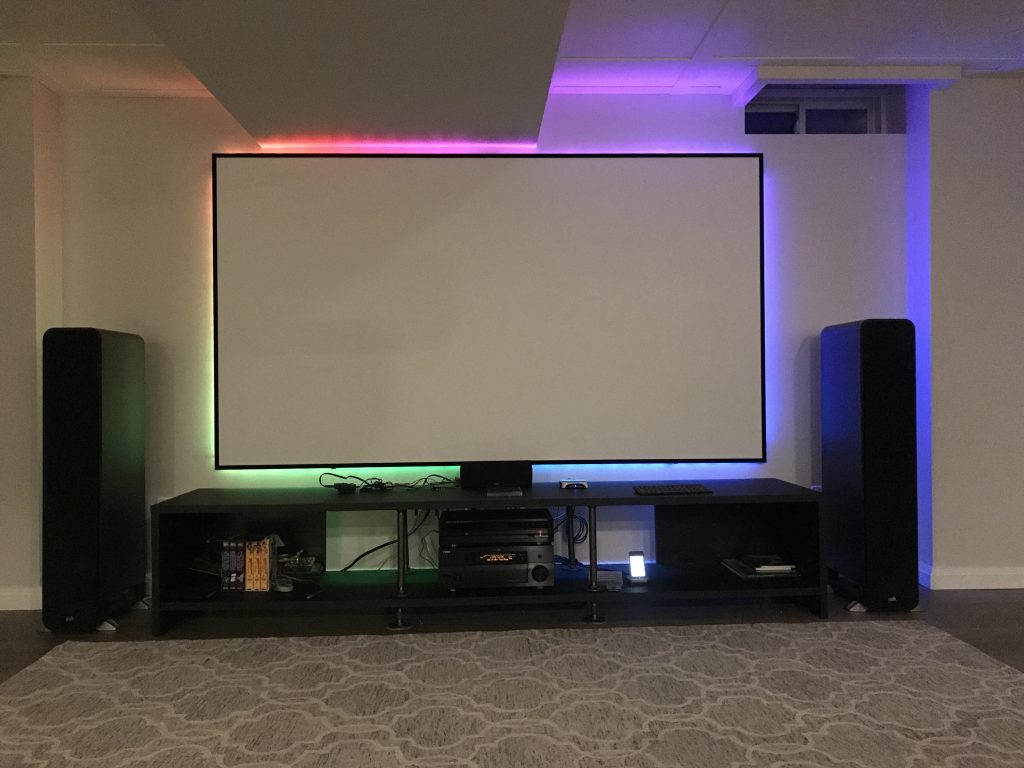
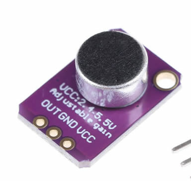
The most common way to take sound and convert it to use for lighting effects is by way of an electret mic – it essentially “listens” to the sound and converts it to analog output that can be processed to display effects using LEDs. The issue is a mic listens and converts all sounds which can make for an ugly visual given all the sounds (including people speaking) are part of that result.
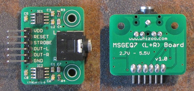
After a bit more digging I came across the MSGEQ7 made by MSI. This little chip processes an incoming audio signal direct from source and outputs 7 frequency bands that can be processed on a microcontroller to do all sorts of things. The item displayed here is a ready-made version composed of the chip and necessary components to get you up and running quickly. For the $$ this was just easier. Have a look at the datasheet to get a better understanding of specifics. It reads the audio signal and processes the output into 7 bands (
63Hz, 160Hz, 400Hz, 1kHz, 2.5kHz, 6.25kHz and 16kHz).
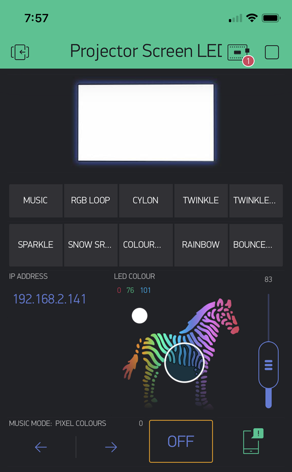
The Blynk app is pretty straight forward. It allows the setting of 10 different mood effects, direct control of colour (see the zebra controller), brightness control, displays the IP address of the MCU in case I want to remotely update it, and also has messaging feedback to report on the status of the device – including when it’s sleeping (as Blynk will not work). The Music option is what this post is all about. It also has different LED colour patterns for this mode (see bottom).
Update: I’ve since migrated this project to use an ESP32 as I wanted to reliably use the MCU’s sleep features as well as easily update the device remotely using OTA – more on this below).
The first strip (216 pixels) goes all the way around the projector screen. The second strip (79 pixels) is under the audio cabinet. I use the Blynk app to drive various mood lighting modes for entertainment, and added in this music-mode option being discussed here. Tip: These NeoPixels can draw a lot of current at full tilt. Having ~300 pixels @ about 60mA each at full, that’s about 18A. I am using a 5V 10A switching power supply which will do as none of the modes will drive all LEDs at full power at once, so there’s lots of room there.
In the sketch, the MSGEQ7 reads the audio signal, splits it into the 7 frequency bands and passes the values onto the MCU (here’s a good write-up if you want to understand more). In my case, I take 2 bands in the array and process their output to each of the 2 NeoPixel strips respectively. Credit to Nazmul’s write-up to help me understand how to make this work for my project.
Since I only want the VU Meter to show on the left and right side of the projector screen, some simple math takes care of this in the sketch (included below) . The screen NeoPixels are tagged to the 160Hz band, with the cabinet strip tagged to the 1kHz band. It seems to work well enough, but I want to do more testing to find the ideal frequencies to represent what looks best.
I’m also looking for options to reduce delays in the code as there’s a lot going on there and I want to make sure the LED response timing match the timing of the sound input with as little delay as possible. It’s currently in the range of < 100ms but I think there are opportunities to reduce that further. There is also an element of sampling to eliminate noise, so it’s a balance quality vs speed.
Build Instructions: ESP32 Version
I’ve now got 2 versions of this project. Both perform similar activities. The original version is based on a NodeMCU Mini ESP8266 (below) and is always powered and waiting for a signal input. This works fine but there are few issues that I wanted to overcome. Namely I did not want it always powered on when I don’t use it that often, and I’m always looking for ways to conserve power. The newer version is based on a DoIt ESP32 DevKit V1 and has additional features including a Deep Sleep feature as well as OTA Updates
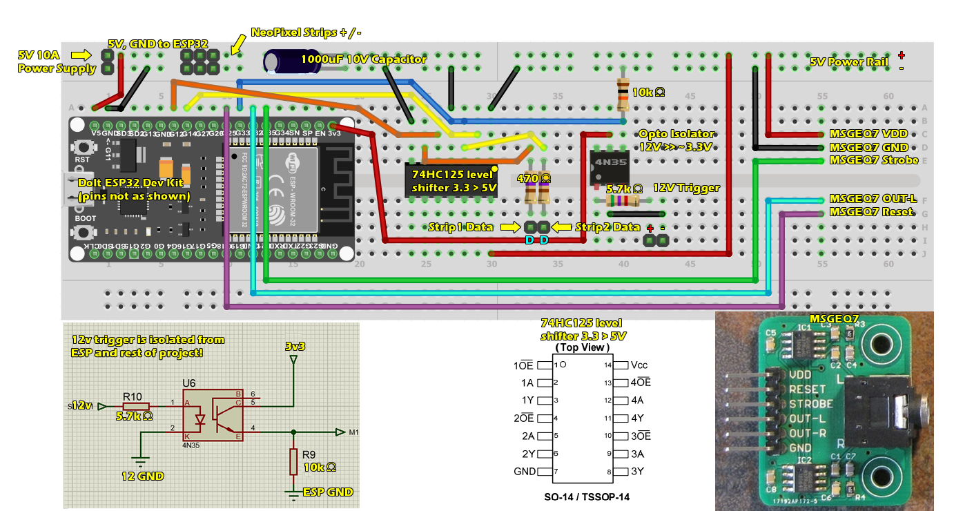
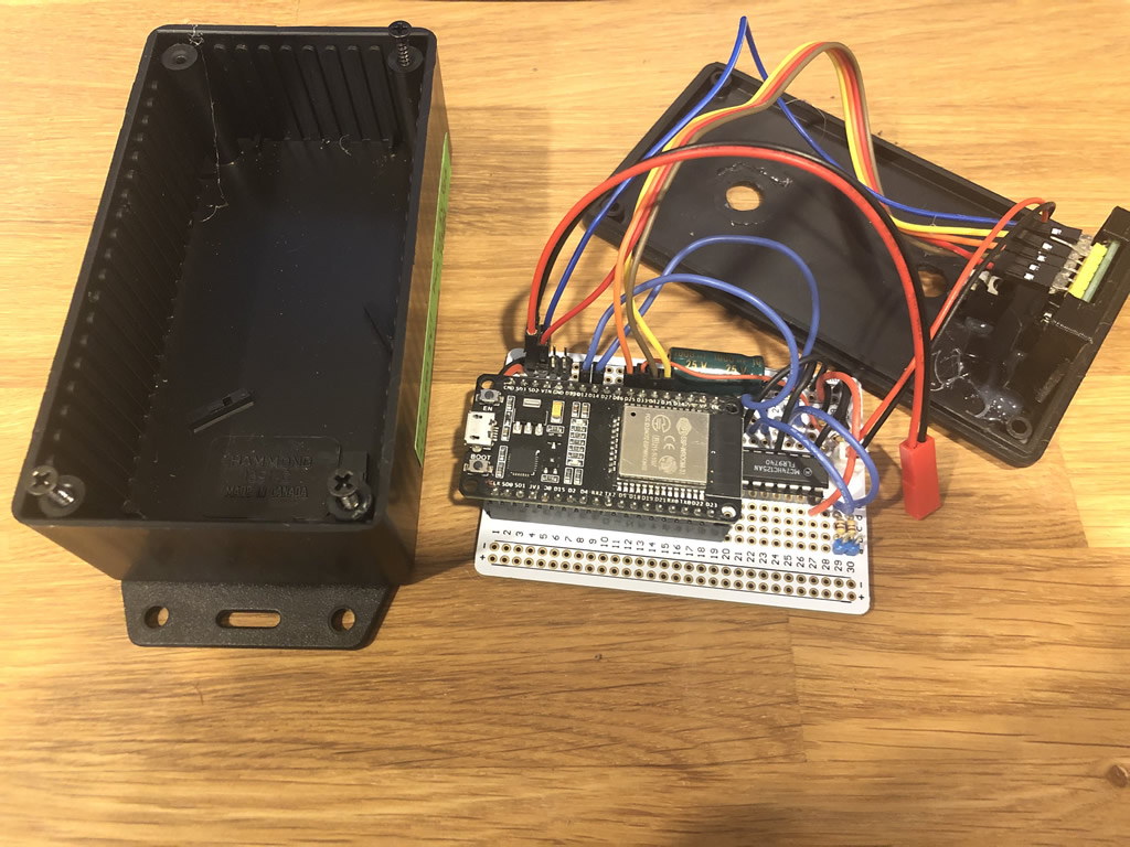
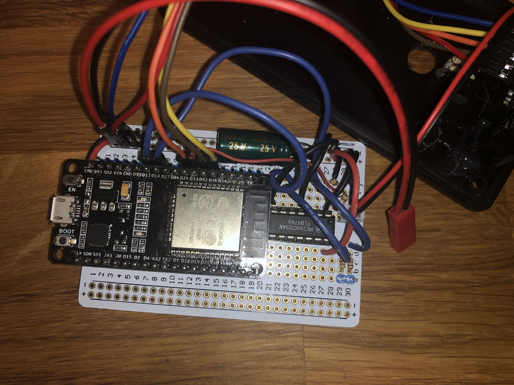
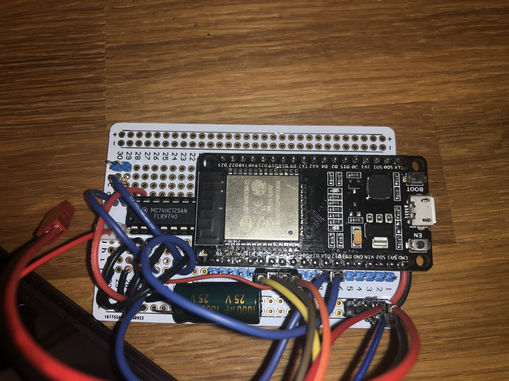
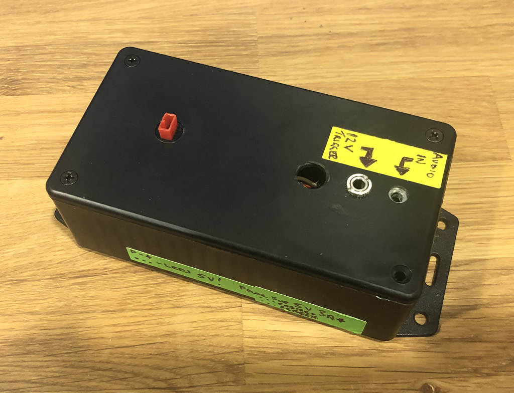
For this build I am using a DoIt ESP32 DevKit V1. However, most any ESP32 will do as this project does not require many pins. Just make sure you take note of the pins you end up using and adjust as necessary in the sketch. The general concept is simple. The MSGEQ7 processes the signal from my receiver into a single Analog pin on the ESP32. The ESP takes that signal and processes it into 7 channels, but only 2 are used. It outputs the data over 2 data lines. It also sleeps after 60 second of inactivity and uses the 12V trigger output from the receiver to keep awake. I use a voltage divider to drop the 12V down to 3.3V for the ESP to read (HIGH or LOW). Change of plan. I decided to switch to a 4N35 Opto Isolator as I wanted to isolate the 12V trigger from my receiver completely from this circuit to avoid noise. It uses the ESP Deep Sleep function with an Interrupt triggered when the receiver Trigger 12V out triggers the 4N35 to send a HIGH (3v3) signal out (more in the code). This version also uses a level shifter as the ESP data pins output at 3.3V and since my NeoPixels are driven at 5V, I needed to step up the output to for the 2 data lines to match.
For this version, you will need the below parts:
| DoIt ESP32 DevKit (or similar ESP 32) | Single or others | 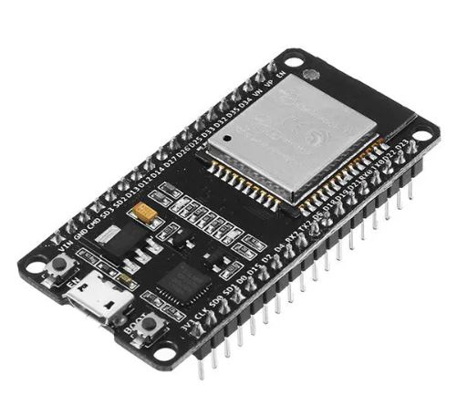 |
| NeoPixel Strip 5 Meter 5V | Here or here or Alternate | |
| MSGEQ7 Breakout (single channel will do) | Single Channel Dual Channel | 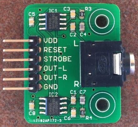 |
| 74HC125 (datasheet) or 74AHCT125 (converts logic from 3.3V to 5V. | link link |  |
| Other bits: 5V 10A switching power supply, jack, 4N35 Opto Isolator, wiring, 1000uF 10V Cap, 470, 560 and 1.7K Ohm resistors, headers, project case. | Source |
The wiring diagram should be self-explanatory. Some additional info:
- MSGEQ7 VDD >> 5V power supply rail
- MSGEQ7 GND >> GND on power supply rail
- MSGEQ7 Reset >> ESP32 D32
- MSGEQ7 Strobe >> ESP32 D25
- MSGEQ7 OUT-L >>ESP32 D35
- 12V Trigger out (from voltage divider) >> ESP32 D33 (~3.3V)
- 74HC125 Pin 2 >> ESP32 D14
- 74HC125 Pin 3 >> 470 Ohm Resistor >> Strip 1 Data Pin (header)
- 74HC125 Pin 5 >> ESP32 D12
- 74HC125 Pin 7 >> 470 Ohm Resistor >> Strip 2 Data Pin (header)
- 74HC125 Pins 1, 4, 7 GND on power supply rail
- 74HC125 Pin 14 >> 5V DC on power supply rail
- NeoPixel Strips VCC(5V) and GND to header pins on power supply rail.
- NeoPixel Data connectors to Strip 1 / Strip 2 Data headers
Download the sketch below and load into your Arduino IDE. Ensure you have the correct libraries loaded. If not, you can use the library manager or GitHub to get them. A lot of hard work has gone into making this project and providing this documentation. Please consider donating a few bucks – a cup of coffee these days 🙂 It goes right back into future projects which means more instructions!
Please read my Disclaimer page.
Your Support is Appreciated: A lot of time is put into developing my projects and the publishing of videos and these build logs. If you use them for your projects, please consider a small donation. It will go to purchasing new things for future projects and help support the work I do here. You can support vai either Ko-Fi or PayPal links below. Thanks!
Build Instructions: ESP8266 Version
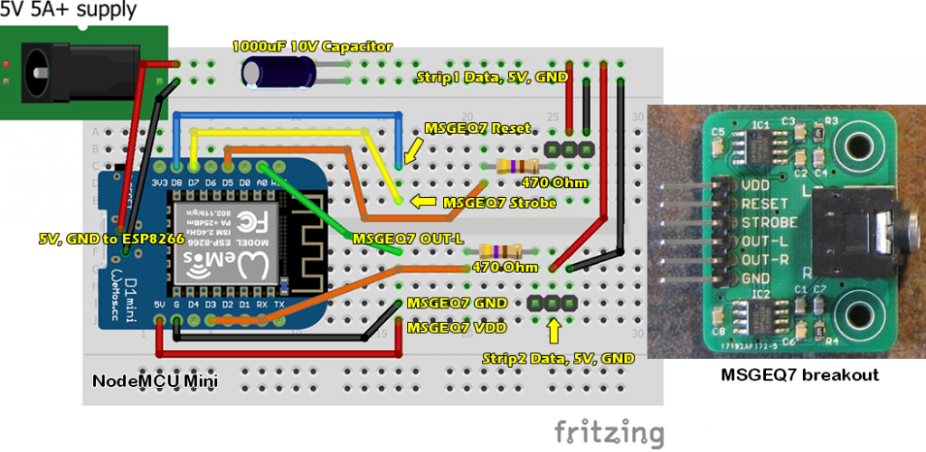
Wiring the sucker up is pretty straight forward. I’m using a NodeMCU Mini (ESP8266) but most any micro controller will do (read up on NeoPixels first as there is some processing power needed). I used an ESP8266 as I wanted to enable control via my phone (Blynk app). Power is supplied by a 5V – 10A switching power supply (don’t buy cheap crap if you care for your NeoPixels!), and feeds into the NodeMCU, both the LED NeoPixel strips and the MSGEQ7 breakout. Connections are as shown above. That’s a 10V 1000uF Cap on the +/- lines of the power supply to protect the strips from surges. Ditto for the 2 resistors shown.
| NodeMCU Mini ESP8266 | Single or 3 Pack | 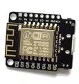 |
| NeoPixel Strip 5 Meter 5V | Here or Alternate | |
| MSGEQ7 Breakout (single channel will do) | Single Channel Dual Channel | |
| Other bits: 5V power supply, jack, cap, resistors, wiring, 1000uF Cap, 470Ohm resistors, headers. | Source |
My Yamaha RX-A2080 receiver feeds a signal out via Zone 2 RCA out to a 3.5mm stereo audio cable and into the MSGEQ7. The below sketch has a lot of bits in it as it covers off the MSGEQ7 music reactive code as well as the Blynk integration with all the other patterns. It’s pretty easy to discover the bits that drive the music piece though.
As I delved into researching what could be done with the MSGEQ7, I wanted to give a shout out to Nazmul and Max for their samples and write-ups that help me understand how to process the output of the MSGEQ7 and some of the things that could be done with this versatile chip and an audio signal. I am also truly amazed with all the samples out there and other makers doing crafty things with this chip, some NeoPixels and an audio output. It blows away the old days of a graphic EQ on a ghetto blaster (I’m giving away my age here folks 😉
Ideas that I’m working on to enhance this:
- Sleep mode: Since the unit would need to be off for the most part, I’m going to use the ESP Sleep Mode. My Yamaha receiver has a 12V trigger out port that I can use to trigger the ESP to wake up and start the routine.
- Since I have more of the screen real estate LEDs unused, I’m going to see what I can do to represent some or all of the remaining MSGEQ7 frequency bands.
If you want to build it yourself, here are the key components for this project:
You can download the Arduino sketch below. Please be sure to give credit where due. Also do not remove any of the reference/credit code at the top. Rename the file with a .ino extension to get started. You will also have to re-create the Blynk project yourself if you want to remote control the lights. Else, you could easily hack in a push button to the controller and have it scroll through the different modes. A lot of hard work has gone into making this project and providing this documentation. Please consider donating a few bucks – a cup of coffee these days 🙂 It goes right back into future projects which means more instructions!
[paypal-donation purpose="NeoPixel Music MSGEQ7 Source - Plastibots.com" reference="Plastibots.com"]


 – Android App to Control Robots")
You use a 74HC125 to use only 2 ports. TXS0102 or 2x TXB0101 are possible substitute. Other solution BSS138 and 2*10k resistor [link removed] . Another solution 74LVC1G126D. So much solutions for the same problem.
Good job!!!!