
NeoBrake Sequential LED Third Brake Light Kit
Third brake light with a NeoBrake LEDs with controller/enclosure and input leads for 12V brake line. Designed for Mazda Miata NC model (can be adapted for different sizes & vehicles). These are custom made kits. Interested? drop me a line. Also check out my NeoLumn8 Rear Sequential Light kit.
How It Works:
The LED sequence triggers on braking (which powers the unit). Video below. When brakes are released the unit powers off (regardless if it was finished a sequence or not – there is no back-up power supply). It works much the same as an existing center brake but has sequences instead. While brakes are applied, after the sequence, all LEDs turn red – again only while brakes are applied. You can select from 9 sequences to save which option you prefer. See below FAQ for important tips and other info.
Changing Sequences: To select a different sequence, the unit must be powered up, so you will need a helper to apply the brakes. See the usage video below which demonstrates the sequences and mode switching.
Sequence Options:
See FAQ note on sequence colours and red lenses.
- Instant On (same as stock -because why not? Think law enforcement getting in the way!)
- Sweep 1 (sweeps from center to outsides)
- K.I.T.T. (Larson Scanner) – think Knight Rider!
- Bounce (bounces from outside-in)
- K.I.T.T. and Bounce
- Colour Bounce (same as 4 but with colours)
- Rainbow Fade
- Double In-to-Out Sweep
- Sweep 2 (similar to #1 but slower)
Installation:
The kit is plug-and-play, but modification is required on your part to install it. This includes cutting open your lens etc. If that doesn’t float your boat, then this kit isn’t for you 😉
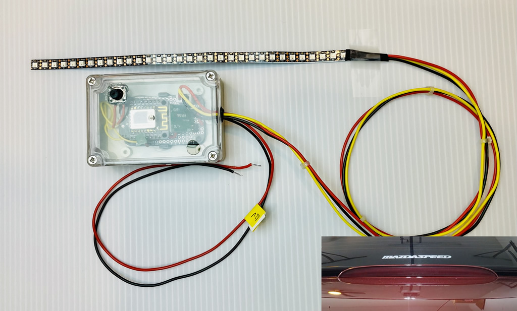
The kit includes the LED strip and controller with an enclosure. It also includes 3M VHB tape (strip mounting) and double-sided velcro for the enclosure. Your job – mod it into your existing rear light enclosure and replace the existing LEDs with this kit. The controller is wired to your brake light connector (12V/GND). The LED strip is flexible and needs to be mounted to some sort of bar. Also note that the strip is conductive in places, so do NOT directly mount it to a piece of conductive metal. Instead use the provided 3M VHB tape. It both sticks as well as provides an insulator so the LEDs don’t short! In the case of the NC, the existing LEDs are mounted on a bar (may be the case for other vehicles). The LEDs can be cut off and bar re-used to mount this strip – just make sure the surface is smooth and clean before mounting the 3M tape. The strip has a connector on it that would need to be run through the existing housing and through the trunk lid. Once done, the hole should be sealed with silicone to ensure moisture does not get in. The controller enclosure can be mounted using the velcro to the underside of the trunk lid. The input power cables (12V and GND) need to be connected to the brake line connectors. You will need t-taps or similar to tap into it. Red = 12V, black=Ground. See the FAQ for important notes.
By purchasing this kit you accept the Limitation of Liability
FAQ:
- Red Lens: If you are mounting into a red lens, the colour sequences will be masked by the red of the lens and won’t likely show well. In these cases, simply select the red sequence options only.
- Reverse Polarity: If you accidentally connect the brake leads in reverse, you will likely fry the power supply. If you suspect this happened, it’s likely the controller and LED strip are still ok (but no guarantees). To test, you can use a 9V battery applied to the brake power leads (correctly this time 😉 ) leading to the controller. The voltage on the output pins should be 5V. If not, you’ve fried your power supply and it will need replacing. Test the controller as it may have also been affected by this. To do this, you can connect a USB power cable to the port on the microcontroller. It should power up and lights will blink. The unit may also run as normal. This is good. If not, then you may have shorted other components. See below.
- LED Strip: If you suspect you’ve blown the strip as a result of reverse polarity, you may still be able to recover the strip. Unplug the strip connector from the main board. Using a voltmeter, switch to Resistance (Ohm), then measure across 5V and GND before the first pixel (use the connector), You may see 0. Do the same now on any other LED in the strip using the pads. If you see some resistance on others, you likely have blown the first pixel. To fix this, you will loose 2 pixels as the sequences are based on an even # of pixels. De-solder the 3 wires making note of which goes where first. Using scissors cut the first pixel off >> BUT >> make sure you leave pads to solder to, so cut to the left of the gold pads. Then do the same and cut off the last pixel. Although the last pixel is optional to remove, if you leave it the sequences will be imbalanced.
- LED Strip: the strips and mounting wires are very fragile. Take care when mounting them into the housing. If you suspect a wire has come loose, it may be able to be re-soldered on, but again use caution as the pads are thin. You can also test for voltage anywhere along the strip. There are 3 pads beside each pixel. 5V PWR, 5V Signal and GND. Test against 5V and GND.


Comments: