
NanoBot
While waiting for the NXT system to come out, I decided to try my luck at making tiny robots. While Googling, I stumbled across a Yahoo newsgroup for NanoBots based on the MegaBitty controller. I have always been int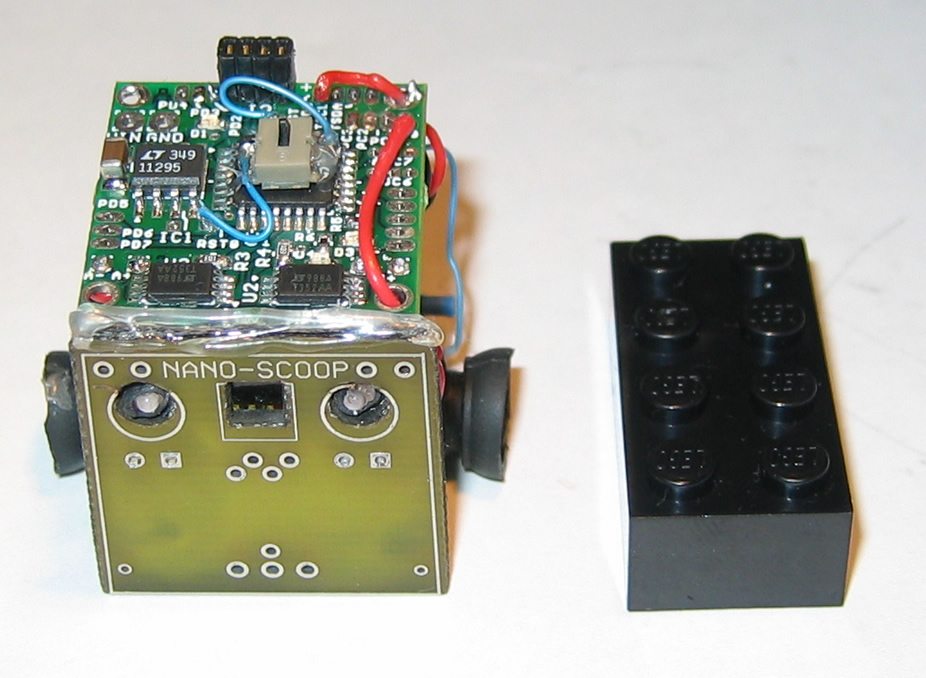 erested in making compact Lego robots, but for obvious reasons, they can only be so small. So, I decided to try my luck and NanoBots. Although I am not sure of the exact definition of a NanoBot, I believe it has specific maximum size limits for competition which is approx. 1 inch cubed (1x1x1). This is my first venture into non-Lego robots. NanoBot uses a variety of pico-sized components including:
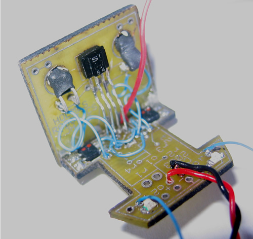
- Atmel Mega 8 Microcontroller
- 2 GWS Micro Servos – hacked into the gearbox below.
- A 3.5V IPOD Shuffle battery unit w/built-in charger.
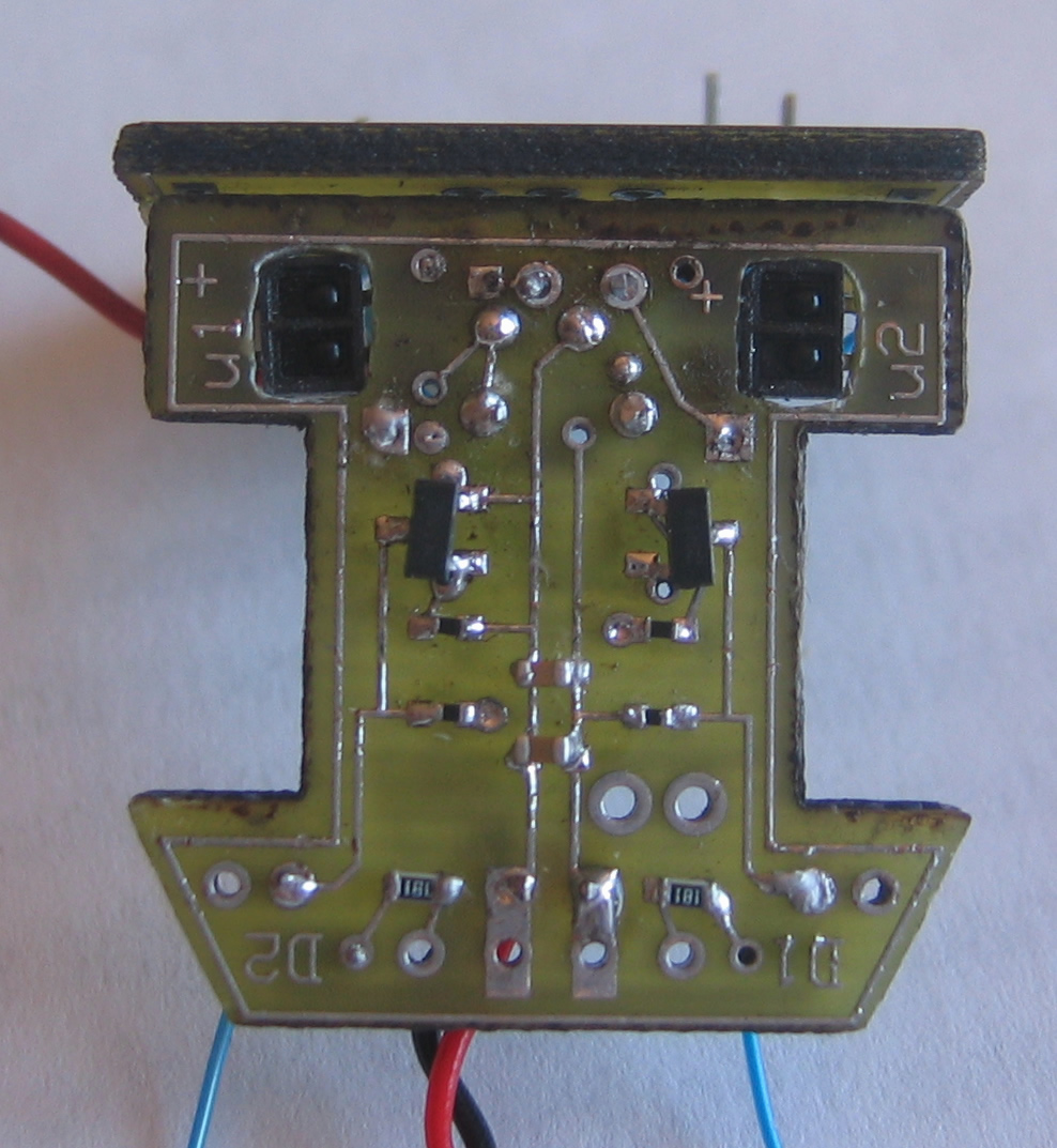
- CJH line and object sensing base and front circuit (uses SMT components)
- None other than Lego minfig wheels
Some of the key electronic components used on NanoBot are:
- AtMega8P main CPU (IC AVR MCU 8K 16MHZ COM 32-TQFP – ATMEGA8-16AC)
- Photointerrupter Line sensor (x2) 424-1096-5-ND
- All caps, resistors, LED’s are surface mount technology (SMT)
For more information on the MegaBitty and NanoBots, check out the Yahoo groups here: MegaBitty There is a video (right >>) that shows it in action.
[ad name=”GoogleAS728x90″]
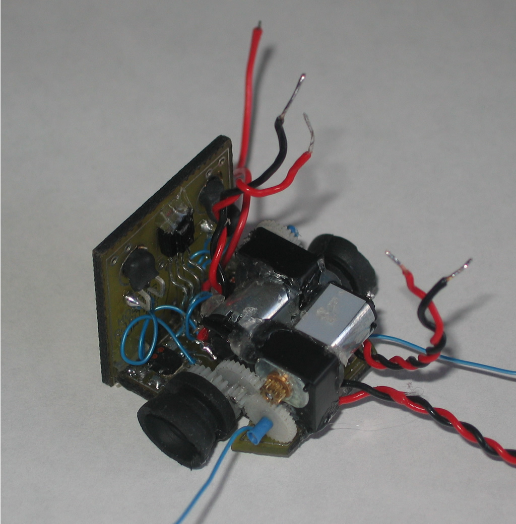
Looking at the base of the robot with the MegaBitty controller board and battery removed, you can see the gearbox and the back of the front sensors. On the front, there is basic IRPD frontal object detection. When running a Sumo program, the sensor is “seeking” its competitor. When found, NanoBot goes to full speed and drive forward until the edge of the sumo ring is detected. (more on edge sensors later). As for the gearbox, it uses 2 hacked GWS Nano Servo’s. The servo’s are originally intended for the RC market, but they are small and great for hacking. In this case, they were literally hacked to pieces. Click the image for a larger view and you can see the glue around it all. Each gear was glued into place by hand, then both the left and right drive motor units were glued together. This was the most difficult part of building NanoBot. Being my first time at it, the drive mechanism could use some re-work. I wanted to use these gearbox units that I pulled from some Panasonic LS-120 disk drives, but they were too large… Instead, I will be using them on my next (larger scale) nano.
Here is a perspective to give you an idea on the size of the components. That is a CDN quarter there. Both the frontal and base boards required manual assembly which including soldering SMT (Surface Mount) components that were as small as crumbs. Often, when working, I would drop a SMT and have to take a magnifying glass to find it as it would get lost in the bits of filings etc that were around the work are. Word to the wise – if you try this, make sure you have a good magnifying glass as well as work in a clean white or black surface.

The battery – NanoBots are typically powered by 5V sources. In this case, I have been able to get away with ah 3.7V LiPoly battery out of nothing other than an IPOD Shuffle. Yep. Had a buddy that decided to jump into the lake at his cottage and forgot he had his Shuffle in his pocket. After several unsuccessful attempts at getting it working, it came to me to see what I could do. The Shuffle batter is perfect as it has the charging unit built-in. So, to charge it, I have a 9V batter wired up with a plug. Just plug the 2 in together and leave them for a minute or so, and bam! Nano had enough charge for several rounds. Caution – LiPoly batteries are volatile when charging. My method is by no means the right way to do it – and not is it safe. If you go this route, do it at your own risk and make sure to monitor the battery. If it gets hot, unplug it and move it outside (LiPoly’s are known for puffing up and bursting into flames!)

Gearbox: Here is a view of the gearbox before it went into the chassis. That’s glue from a glue-gun all over the place. The entire motor, gear and drive shaft assembly is held together by the glue itself. Not my best piece of engineering, but it works and gear slip is limited. It has the strength to push 4 2×4 bricks stacked as a block and then some. I have not tested its power as of yet, but it can at least push its own weight around. I believe the weight limit is 100g. NanoBot is probably 80 or so.

Rate This Post: 
 (5 votes, average: 4.60 out of 5)
![]() Loading...
Loading...

Great post! I recieved alot of cash for the holidays and I think I want to buy this. Your wrote a awesome entry, definitely the best Ive seen so far. I will be looking forward to your next entry. thank you again.
We just couldnt leave your website before saying that we really enjoyed the quality information you offer to your visitors… Will be back often to check up on new stuff you post!
Nice blog adding this to my twitter now