
WIoT-2 Weather and Home Automation – Nextion with ESP8266/ESP32
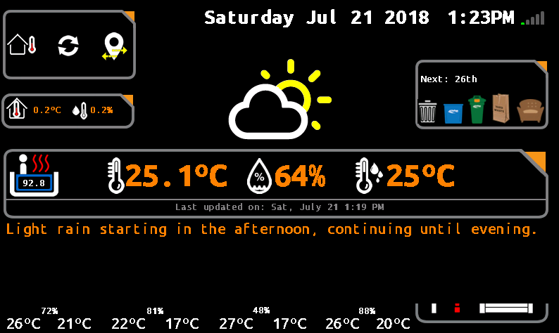
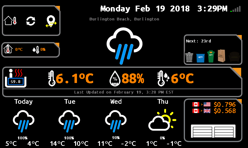
This is a continuation from my first iteration of WIoT weather station. What is WIoT-2? I use it as a cloud-connected (IoT) info center of sorts. It is a culmination of information my wife or I often look for either on our way out of the house, or when we come home. It displays current/forecast weather, temp/humidity from outside the house (this), date, time, our local waste collection schedule, currency rates, the status of our garage doors (this), and our hot tub temperature (this). Read on to find out more about how I built it.
Notice: As of Jan 2023, Blynk legacy app is no longer available, so any parts of the code with Blynk will not work and would need to be converted to the newer (paid) Blynk system. It can be removed however.
Skip the Fluff. I want to Build It!
2020 Interface
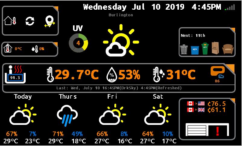
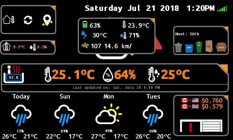
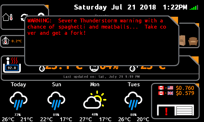
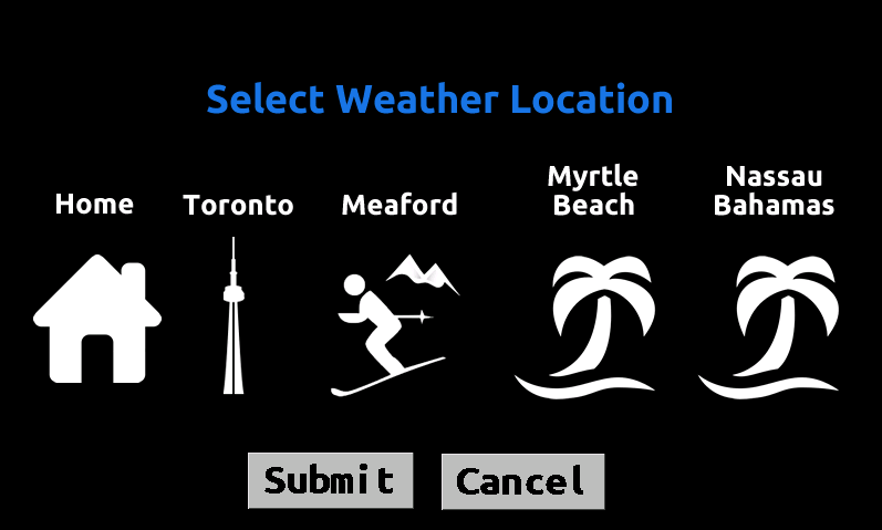
| Outside Temperature Data | Storm Alerts | Change Location |
 |  |  |
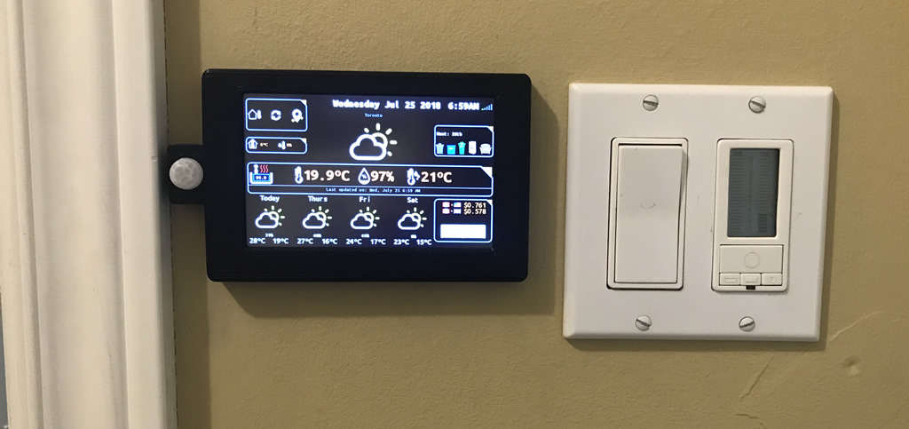
| Daily Weather Detail | WIoT-2 Mounted | |
 |  |
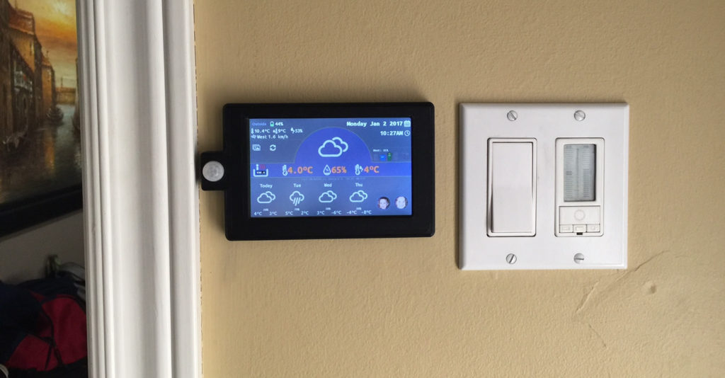
WIoT-2 In Action
2017 Version – Mounted to Wall
WIoT2 Features:
- Display current and forecast weather information + alerts.
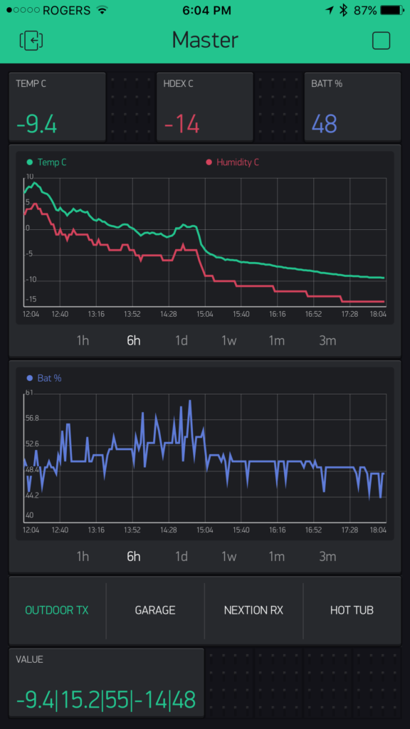
- Display weather data generated outside the house via another ESP unit. It polls temp, humidity and battery info (it’s solar powered) – Integrated with Blynk
- Allows change of weather to different locations (because why not?!)
- Displays temperature and humidity from inside the house. Watch out Nest! 😉
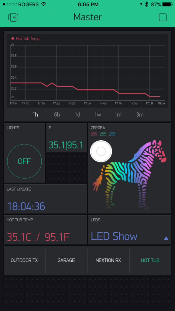
- Poll and display data from our hot tub (integrated with Blynk)
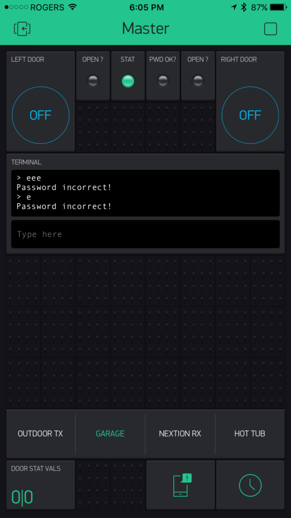
- Open/Close my garage doors, poll/display the status of our garage doors (open/closed) (integrated with Blynk)
- Allow our kids to interact with the unit – sends notifications via Blynk
- Polls waste collection calendar information to show us which waste items are being collected on a weekly basis.
- Show the current date and time – uses Blynk RTC widget
- Shows up-to-date currency conversions CAD>USD, CAD>GBP.
- Master control center for net-connected power outlets in my house (coming soon with SONOFF integration)
- Displays counter for WordPress site views. (Would likely work for any site that pumps out JSON stats)
- Jan 2021 – Now supports web-based OTA updates (ESP8266 only – but code is commented for removal)
About the Nextion TFT Display:
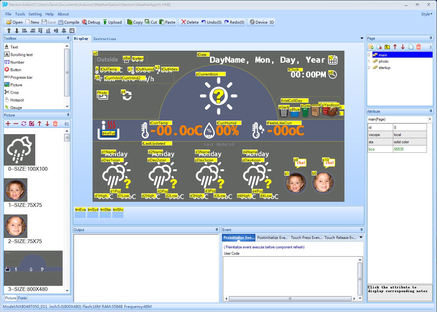
I came across the Nextion display over a year or so ago during their Indiegogo campaign. At the time I passed it by as there was not enough information, and frankly I didn’t understand the approach. In hindsight I regret that decision. Itead hit the nail on the head with this display as far as I am concerned. It connects to your MCU (Arduino / ESP8266/32 etc) using a standard 4-wire serial connection as is easy-peasy to program/control. It uses simple serial commands to communicate between the MCU and the display – which is perfect for my needs (and I think most makers like myself). It uses their custom HMI editor (below) which allows you to layout all graphic elements/buttons on the TFT. You can also setup multiple page views to make a very robust visual interface. Refresh and image load rates are fast as well. The concept of using their HMI and how you put graphics and text elements is a lot like object oriented programming, so it was easy to pick up. For those of you using RA8875/1305s and others, you don’t know what you are missing. After spending countless hours coding a prior project using the RA8875 controller, the Nextion is a walk in the park and makes graphical layout and interaction much easier than any other I have dealt with. Anyway, enough on this. I’ve done a more fulsome write-up as to why I like this display so much. There are many other advanced features of the Nextion that I won’t get into here as this is not the purpose of this post.
 | 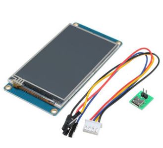 |
Pin-Outs & Connections:
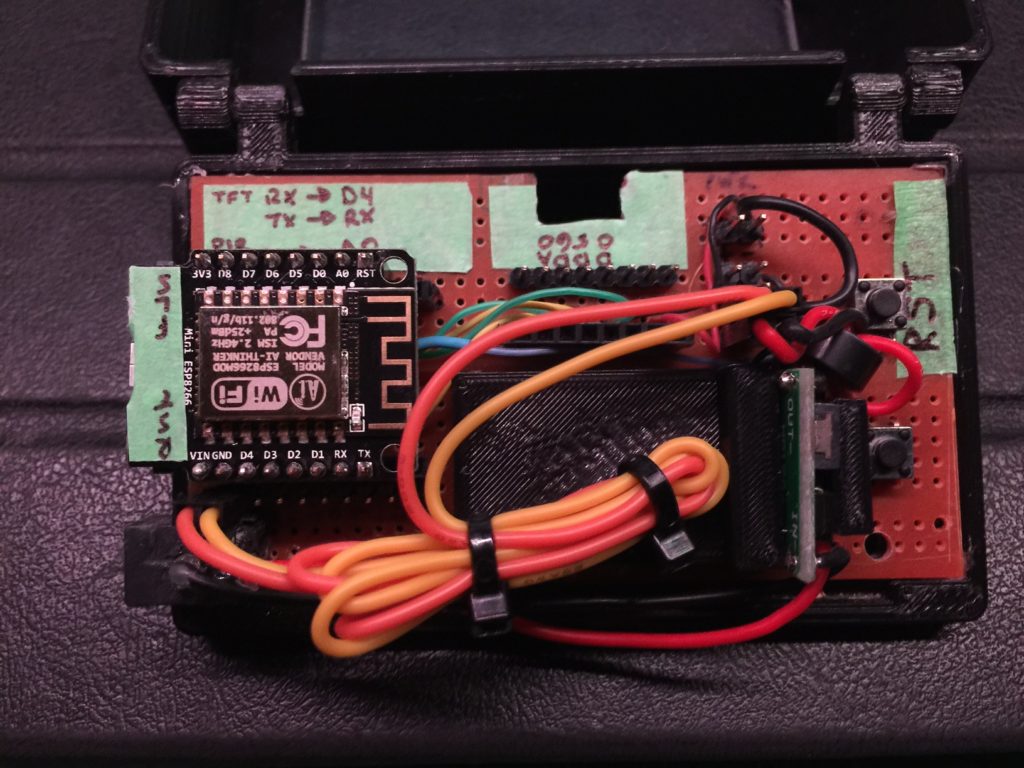
One of the best things about this project is how easy it is to put together. The connection to the screen uses standard serial (PWR,GND, RX, TX). Then connections to my sensors (PIR 3 wires), Temp/Humidity Sensor (3 wires). Easy peasy!
I’m using the NodeMCU ESP8266, so your connections may be different. It also works with the ESP32. This project takes advantage of both Serial ports. Serial is used for comms between the PC and NodeMCU, Serial1 is used for comms between the MCU and Nextion. Well, not exactly. The Node’s Serial RX line is shared on both sides. More on that in a bit. The connections are Node RX to Nextion TX, and Node D4 to Nextion RX. The sketch uses hardware serial using Serial1 (TXD1) to transmit to the Nextion, while return data comes over Serial RX. It sounds more complicated than it is… In the sketch, both Serial and Serial1 have been created. The only trick is that you cant have the Nextion powered when uploading sketches to the Node. I solved this by inserting a latching switch on the Nextion 5V power supply.
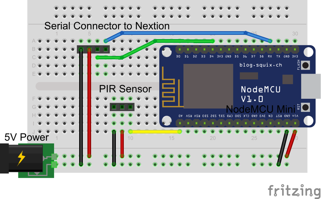
Important: Don’t fall into this trap! If you are powering your MCU and Nextion by different pwr sources their GND connections must be common (connected)! Also ensure your power supply has sufficient current to power the Nextion, your MCU and sensors. My go-to is a 5V 3A power supply which always does the trick for me. Also, don’t underestimate the MCU demands on current when it’s using WiFi. The Node jumps to ~500mA when getting data. Here are the connections between the MCU and Nextion: NodeMCU RX >> Nextion TX. NodMCU D4 (TX1) goes to Nextion RX.
Hardware:
- NodeMCU ESP8266 V1.0 – MCU (should work with other Wifi-enabled MCUs with minor code modifications). Memory capacity is key – hence why I chose an ESP.
- Nextion TFT LCD Find out why I like these displays so much.
- Tiny PIR sensor.
- DHT-22 Temp / Humidity Sensor.
- 5″ Bezel 3D Printer – STL
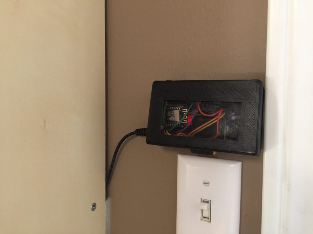
- You will have to build a case to house the MCU and power supply components. In my case, it is on the other side of the wall.
- Switching power supply – provides 5V to NodeMCU and Nextion
- Also works with an ESP32 with minor code modifications.
Libraries & Resources:
- Nextion Library – Note there is an official Nextion library as well, but this one was sufficient for my needs given it allowed for me to send and receive information from the Nextion. Be sure to read the notes and links (link, link) provided as they give great samples. Note: You can use software or hardware serial. I used hardware serial in my code. If doing this you have to comment out a line in Nextion.h //#define USE_SOFTWARE_SERIAL //Comment this line for use HardwareSerial
- Blynk Library – I use the app to control and monitor the hot tub, garage and others components.
- Time – you will also need Paul Stoffregen’s time library for Blynk:
- Arduino IDE – I used 1.6.13, but others should work fine as well.
- Node MCU firmware – comes as part of the ESP package. Google is your friend if you need help. Just google setting up NodeMCU in Arduino.
- Arduino JSON for parsing the JSON data.
- Nextion forums – (a big shout out to Patrick and Steve for being so helpful in getting me up and running).
- Nextion Enhanced Support – for when you need that extra help!
- Arduino Source Code & Nextion HMI file – see bottom of page.
- WIoT is now integrated with Weatherbit.io. Prior versions used DarkSky.net (also available) and OpenWeatherMap.com. DarkSky has since closed its’ free API.
Blynk Integration:
The project uses Blynk for viewing the status of many of my devices. However, it can be removed. It also has controlling features (hot tub lights, garage door opener etc). I also use it to debug the devices to ensure they are still sending data at their defined intervals. You don’t have to use Blynk, and it’s easy to modify it out. In this case it simply extends functionality of WIoT and also serves as an alternate controller.
| Outside data is also logged to Blynk. Temp, Humidity and Battery are tracked. Data also reported to WIoT. | The Hot Tub controller monitors the temperature and allows the RGBW NeoPixels to be set. Data also reported to WIoT. | The Garage Door Monitor allows for monitoring and controller both garage doors. Data also reported to WIoT. |
Challenges:
I had my first challenge with the NodeMCU when trying to both display debug messages using the standard Arduino Serial window and trying to communicate with the Nextion. After some digging and help from Steve and Patrick on the Nextion forums, I was able to get both Serial debugging and comms with the Nextion. It uses a simple trick in that the Nextion uses the NodeMCU’s D4 pin (Serial 1 TX) to send comms and Serial RX to receive. For those with a keen eye, you can see that this is a problem when uploading sketches – which is easily solved by either disconnecting the pin, or powering down the Nextion display during sketch uploads.
Tips n Tricks:
Changing IDs in the HMI Editor: If you haven’t come across this, you will! For the Nextion HMI Editor, once you dump pictures in there, picture order counts as they are all identified by their ID and that ID shifts if you try to shuffle pictures around. Hopefully you don’t have to, but it may be necessary. Using the code sample below to demonstrate, I discovered that the below approach messed up each time I add or shuffle picture objects in the editor. Instead of using the ID of an object, I have the HMI send a print call when any button click sends content back to the MCU. This way, I can check for more realistic values in the call-backs. i.e. I can send “print b1” when button 1 is pressed. You can use whatever text you want, and you can have separate calls when buttons are pressed or released.
Adding New Images / Image Layer Ordering: As I have modified this project regularly since inception, I have also added new images. The issue is the Editor does not have a robust system for moving images up/down layers to put them in front or behind others. There’s a trick to this however. First off, you can replace existing pictures with new ones. So, if you are doing a refresh of an existing image, use the replace feature as it maintains the image ID and does not mess up the others. This is important if your code refers to pictures by their ID # like this code does (for the weather icons). Now, if you go to add a new picture, it will appear on top of all the others. There are up and down arrows at the top left of the Editor that allow you to move objects to the top or bottom of the object display order. No – you can’t do it layer-by-layer, but hopefully they will fix that at some point. Instead, you can use an approach to move the new picture to the bottom, and move others over top of it (if that is what you are looking for). WIoT2 is complicated as I use a background picture that covers the entire screen, so I have to move the new image I added to the bottom, then select the background image and do the same, then any images I want on top of the new picture I simply selected them all and clicked the up arrow. This would be much better if I did a video, wouldn’t it? 🙂
Nextion Baud Rate: You can view the default baud by referring to the ‘baud’ command in the Nextion Instruction Set. Good news is you can also change it by issuing the bauds command with the baud rate you want to use. Don’t forget to update the baud rate in your sketch for Serial1 (i.e. Serial1.begin(9600);). Default from factory is 9600. I changed mine to 115200.
Using Nextion Editor and an ESP in Debug Mode: I discovered this late in the game, but the Nextion Editor has a feature in Debug view that allows you to simulate in a live environment connected directly to your MCU. Doing this is pretty straight forward. In my situation, I have WIoT2 mounted to a wall, so updating it is a pain. To solve this, I have a 2nd NodeMCU unit. I modify the Arduino code and upload to the MCU. The Serial pointer has to change to use the USB serial connection (in the sample code below). After updating the NodeMCU, connect it to USB and your computer. In the Nextion Editor, open your HMI file in Debug view, select the COM port your MCU is connected to and the correct baud rate and you are in business. Your MCU will feed the HMI real data as if it were directly connected to your display. You can watch the virtual display update. When everything looks good, you can build the HMI file and upload it to the physical screen. The only drawback is if you use sensors and do not have back-ups to add to your spare MCU. For me it did not cause issues, but something to think about.
So.. You want to build it Yourself? Source Code Arduino Sketch / Nextion HMI:
Having spent well over 100 hours and nearly a year developing this project, I’ve taken a different approach on this one as a lot of hard work has gone into this with over 80 versions. For a small PayPal donation of $5 or more (c’mon, it’s a Starbucks coffee… :-), I will share the Arduino sketch and the related Nextion Editor HMI file. Click the PayPal Donate link below, and once received I will send you the code. Thanks! 🙂
Please see my Disclaimer page.
Update July 2020: The latest build now supports Weatherbit.io. You will need a free API key from them.
Update April 2020: Heads up folks! Just found out DarkSky was bought by Apple. As usual, they are out for profit and have stopped providing free API accounts. As a result, if you don’t have an existing account, you won’t likely be able to use this code. Over the coming weeks, I’m going to look at alternatives (https://www.weatherbit.io/) to see who is providing reliable & free data and will convert when I find something. That said, if you still want to donate and convert for your own weather provider, there’s a lot of good examples in this code.
Update March 2020: Fixed! Discovered the noted issue below was related to a problem with WiFiClientSecure. After adding the call darkSkyClient.setInsecure(); inside the connection calls to DarkSky, all is good now. You can use the latest ESP8266 boards. Stay safe folks! Gone with #Covid-19!
Update July 2018: WIoT-2 was original built using Weather Underground data. They no longer offers free weather data API access (existing members are ok). After comparing WeatherUnderground (WU), OpenWeatherMap.org, and DarkSky.net, I landed on DarkSky as they are still free to use and had better data and data type selection. OpenWeatherMap was not quite there yet (seems it’s data sources are limited). Given WU is no longer free, DarkSky was the clear winner.
I’ve now forked my code using the DarkSky.net API (I still have a stable version using Weather Underground as well). I’ve also made strides at streamlining the code and improving memory usage (never thought I would have to say that for an ESP8266!). I’ve also got it working on an ESP32 (needs 2 lines of code changed). You will get the DarkSky version as well as the new HMI. Questions? drop me a line.
What you can expect:
- Arduino sketch
- This code contains various functions and tricks working with strings and char arrays. It’s a result of many hours researching how to do specific tasks.
- Connecting to Weather Underground and parsing JSON data
- Blynk connectivity including interfacing with 2 other IoT devices. (Can be removed)
- Communicating with the Nextion display.
- Robust debugging mode.
- I now use this code as reference for my projects due to the variety of working with string/char array data and manipulation of them.
- You will also need to download the required libraries included in the sketch.
- The latest version demonstrates dynamically parsing a large JSON dataset with limited memory and how to overcome those limitations with clever use of ArduinoJSON features and stepping through the JSON Buffer. This is something I struggled with in earlier versions and used workarounds to make it work.
- Nextion HMI file (developed in Nextion Editor v0.53)
- You get the HMI file that interfaces with the sketch. This version is for the 5″ regular Nextion TFT LCD. However, it should work with other Nextion units (i.e. Enhanced). I’ve provided links above to where you can buy one at a good price and reliable seller. Note: If you decide to go with a smaller screen, you will have to re-work the interface. Nextion Editor is not able to automatically re-size for you.
- You will get the HMI with graphics/fonts embedded. However, you will not get the source graphics used to create the application. It’s up to you to create your own graphics if you want to change what is in there.
- WIoT-2 has some nice features such as the dynamic pop-up windows when checking outside temperature as well as clicking the alert symbol. It demonstrates effective use of real estate on a single screen and provides more information without navigating away from the home screen.
- Setting Expectations
- I’ve create a How-To below which should get you up and running. The hardest part will be waiting for the parts to arrive! 🙂
- If you use this in a project, please give credit where due to those who wrote the libraries as well as myself Plastibots.com. You must retain the information at the top of the sketch, and you may not sell this code to others or use it for commercial purposes or for profit. If you wish to do this, please contact me. It is up to you to investigate usage restrictions for the respective included libraries. I also encourage you to support others who have made our hobby easier and more fun by donating to them as well.
- I am constantly updating this project, and this blog, so the pictures above may demonstrate new features that may not be included.
- Note – the sketch is built for a NodeMCU v1.0 ESP8266. There are comments in there to make it work with an ESP32 (I got it working on a DoIt model). It should work with other MCUs like the Adruino MKR1000, but you may have to do some tweaking. Keep in mind , it uses the ESPs 2 hardware serial lines. One for serial debugging and the other (Serial 1) for Nextion comms.
- Do not expect this code will be plug-and-play. It integrates a number of things such as Blynk-connected projects, the Nextion and sensors. Blynk is easy to setup and comes with lots of examples.
- Sketch and Nextion HMI will be sent within 24 hrs or less of receiving notification from PayPal.
- Donation will appear to dast****1@cogeco.ca.
- The intent of this code is NOT to provide you with a plug-and-play solution. However, it will work if you buy all the same hardware and follow the configuration steps in this blog and below. The intent here was to share useful functions and ideas that you can use in your own code. If you choose to try to re-create WIoT-2, that is great, but please don’t expect free support. I am happy to provide some basic guidance, but this project requires an intermediate skill level. The intention of this donation is to get access to a wide variety of useful functions. This donation is for code, not support 😉 There are plenty of resources online – Google is your friend! 🙂 Again, look below for a How-To on getting up and running and remember, where’s the fun in a ready-made solution anyway!? 🙂
WIoT-2 How To
Due to popular demand, I’ve added some notes to help you re-create WIoT-2. It is not as complicated as it looks – I’m just verbose.
- Parts: At a minimum, you will need a NodeMCU Mini and a 5″ Nextion TFT (links are above). You could use another size Nextion, but they layout would have to change. You will also need a 5V 1A (min) power supply. A PIR sensor would be useful, but you don’t need it to make this work. It is only used for dimming the screen. You’ll also need to get a bezel or print one of your own (links above for the STL for the one I printed). You will also need a MicroSD card.
- Nextion: Download the Nextion Editor. Using the Nextion Editor, open the HMI file provided, compile it. Then select File>Open Build Folder and copy the .tft file to a MicroSD card. Then take the MicroSD card, insert it into the Nextion, then power the unit up. Watch the screen as it updates progress. Allow it to load the file, then power it down and remove the SD card. Note: you can use the HMI on other sized (base) Nextion displays, but you will have to modify the HMI file / graphics to fit, as it will throw errors. BTW – if you don’t have your Nextion yet, you can still connect your MCU to the Editor in debug mode to view it working. How cool is that!? I did a how-to video above.
- Accounts: You will need a Weatherbit.io API key as well as download the Blynk software (iOS or Android). If you plan on using the Blynk bits, you need to create a new project and get an auth key. See #5 for where these are entered. Alternate APIs (may require modification to code)
- Blynk (optional): The Blynk app itself is not included as part of this project as it would not apply since you would also have to create 3 other hardware devices! However, it’s used for basic features and comms (i.e. RTC). In the code, I have my Hot Tub monitor, Outside Temperature and Garage Monitor projects all integrated and sending info to this project. In your case, you can simply ignore it and remove the Blynk related code later once you are comfortable with the project. At the minimum, you will need the RTC Clock and Notification widgets added in your Blynk project as they are used in WIoT. You could simply create a blank Blynk app, add a RTC and Notification widget and use it’s auth code as well.
- NodeMCU and Arduino Sketch:
- The sketch has lots of comments within. It also had a debugging mode with lots of output to help you work out issues (instructions in the sketch)
- These instructions assume you have the Arduino IDE (1.8.5 or >) installed and that you have a grasp on Arduino programming.
- Note – although this was developed using the NodeMCU, it should work for other WiFi enabled MCUs (i.e. ESP32, Arduino MKR1000 etc) with little change. Just be careful as these weather services require a lot of memory. Compare your selection against the ESP8266 NodeMCU memory features before purchasing.
- Connect the NodeMCU to your Arduino environment. Note the NodeMCU uses the CH340 USB drivers for Windows. I suggest running the sample blink sketch to test your connection. I encourage you NOT to try jumping right into this project. First make sure each component is working separately.
- Download and install the required libraries. You will have to make changes to the Nextion library for your Serial connection. Read the details above (scroll up).
- The NodeMCU will communicate to the Nextion using UART1 which is Serial1 in the sketch.
- Sketch: Ensure the Serial1 value is set to the right baud of your Nextion. Refer to the ‘baud’ command in the Nextion Instruction Set, find the Nextion’s baud rate, and then set the value in the sketch. i.e. Serial1.begin(9600); Default from the factory should be 9600. I suggest you change the Nextion baud to 115200.
- Ensure this line is un-commented: #define nextion Serial1 //use this when live on MCU + Nextion TFT LCD Hardware. This is the connection to use when your MCU is connected to the physical Nextion.
- Optional: Connect the PIR sensor to +5V and GND. Connect the PIR data line to A0 on the NodeMCU.
- For the time being, don’t connect the Nextion screen to the MCU.
- You can refer to lines 51-57 to set timeouts for the various data parsing activities. For example, weather is refreshed every 900000 ms (15 minutes).
- A few lines down, you need to set your WiFI SSID and password.
- You also need to enter the Blynk Auth code here: char auth[] = “YourBlynkAuthCode”; You can email this to yourself from the Blynk app you created.
- Further down you need to enter your weather provider API key: const char WU_API_KEY[] = “YourWUAPIKey”; .
- The default weather location is set for Burlington Ontario: char WU_LOCATION[] = “pws:IONTARIO1260”; .
- The section covering waste collection is a bit complicated, so I’m not providing guidance on it as it won’t apply to you as it is specific to local Burlington waste collection. You may want remove the related code later once you get things working. I suggest keeping it there for now as it will work as is. Then remove it later when you have a stable setup.
- Now’s a good time to save save save and version your code!!! I also suggest you save a new version with each successful iteration you have.
- This should be enough to get you up and running. Upload the sketch, then connect your NodeMCU to the Nextion using the pin-outs referenced near the top of this post.
- Always remember to disconnect the power from the Nextion when uploading new sketches. Serial comms will cause it to fail if you don’t.
- Have fun and good luck and welcome to your own WIoT Thing!
- Note: This is not a commercial product and neither my code or notes within this blog post carry any warranty. It is your responsibility to ensure you have purchased safe, certified parts, that you know what you are doing, and that you have ensured the hardware are safe from shock, fire etc. This is not intended for commercial use. There is no guarantee on this code, or it’s safety, or the safety of this code and hardware used. It is also your responsibility to ensure this is safely mounted and uses a certified power supply. It was not designed or tested to be used for critical systems or systems where safety of people or sites are a risk. This was also built using low voltage components. As many folks use IoT devices/apps with high voltage applications, please make sure you know what you are doing. High voltage systems can easily kill you.
- So you have it working now and you want to tweak things?
- You can refer to the void processNextionMessages() function. The purpose of this is to listen to print messages sent back from touches etc on the Nextion and process them. You can see the names are pretty clear and their functions. You can also use this to change the other weather locations that can be changed on the fly.
- Once you have this stabilized, you may want to remove the code related to the hot tub, outside weather and the garage door monitor components. I suggest doing this methodically and saving new versions as you go.
- As noted a few times prior. Don’t spend hours writing code hoping you have it right, only to find it fail and you have no idea where the failure is. Take it in steps. Get a feature working, and save a new version. Then move on. Once you have it all working. Save again! Then, if you are not creating the other projects (i.e. the Hot Tub piece, the Garage piece) you can start to comment out related code, test, then save when it works. Repeat. This is a large project, so take it methodically.
- Troubleshooting / FAQ:
- Getting nothing on the Nextion:
- Did you ensure the right serial speed was set as noted above?
- If you are powering both devices separately, their grounds must be common. I suggest 1 5V power source with >1 Amp supply.
- Your power supply may not be able to supply sufficient current. At least 1 amp is needed. Don’t expect your computer’s USB port to power both the MCU and the Nextion as it typically supports 500mA max.
- If the Nextion screen is blank, try loading one of the default sample .tft files and apply 5V and GND. You should see it show. If not, something is wrong with your Nextion.
- Nextion is not updating with recent data:
- Again. Ensure the correct serial setting as noted above.
- Ensure you have followed all steps above. Particularly the #define Serial1 note.
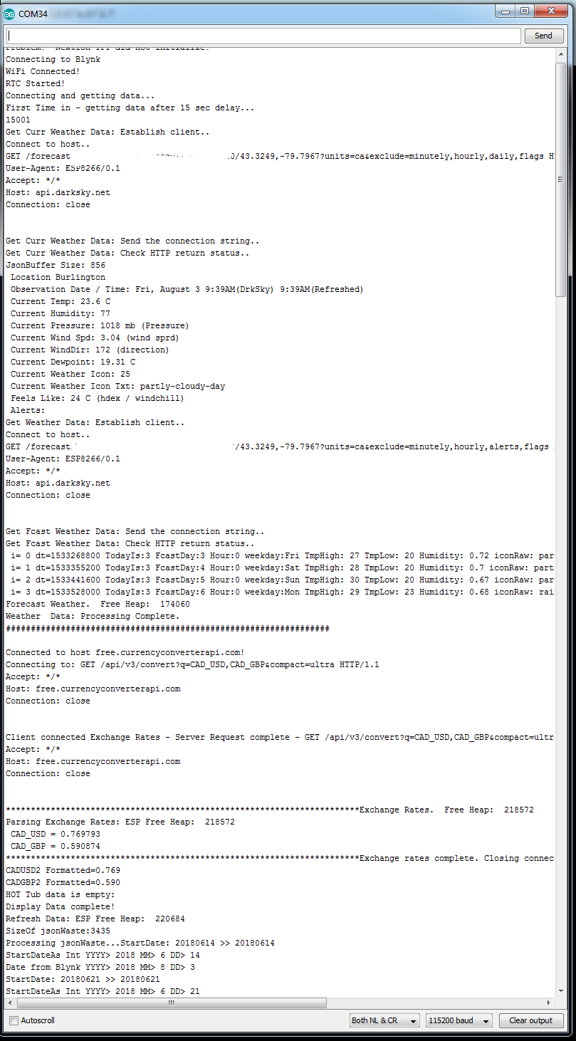
- Try debugging the sketch. Disconnect the Nextion power, change debug = true, in the sketch, download it, and run the open the Serial console. Follow the results to see if the data is being parsed correctly. I’ve got verbose debugging in there which should allow you to see all the output being generated.
- WDT and other resets when debugging via Serial Console:
- Debugging over serial require you to plug the MCU into the computer USB port. Most of us stop there and dont bother separately powering the ESP. Computer USB power supplies typically provide 5V 500mA max. For ESP units, be cautioned that they can draw a lot of current when connecting to WiFi/transmitting data. I’ve seen numerous WTD resets that were mostly resolved with the correct power supply. my ESP spikes over 500mA at times – which coincides with many of the resets I’ve experienced during debugging . Usually when it attempts to get weather data. In a nutshell – when debugging over Serial, dont always assume a reset is a bug in your code. Check your power supply. If necessary connect in a 5V 2A or more unit into your project.
- Using yield()
- If you experience resets in code, it’s likely because you are using delay() or other activities are taking too long. You will see I use yield(); extensively in WIoT-2. The ESP8266 needs to pay attention to the IP stack (and connection). If you don’t let it, it barfs! Throw yield(); calls in code you think will take time (especially while loops etc). …and restrain from using delay(). Look at using timers and other features to get the same thing. Note yield() is depreciated for ESP32, but won’t cause issues if it’s still in there.
- I let out the black smoke:
- Let’s hope you didn’t go there… You’ve provided too much voltage to the device, or you’ve shorted a pin. If you choose a device other than the NodeMCU, it may be only able to support 3.7V max. ie. a raw ESP8266. Not much I can do to help other than comfort you that we have all been there at least once… I often order > 1 unit to ensure I have backups.
- Getting nothing on the Nextion:


HI. Can you send me your sketch ? TO j****@gmail.com Thanks
Details on obtaining code are above.
Hello
Does it work with nextion 2.4 inch?
Yes with some mods. The Arduino side of things will still work fine. However, WIoT was designed for the 5 inch screen which means you’d have a layout issue. You would have to modify the layout and shuffle things around to make them fit.
I have a Nextion display but haven’t done anything with it. I got it a year ago. I don’t think it was mature enough at that time either. After finding this I may give it a shot again. Thanks. Great project.
I have been looking for a full function internet weather station. So far, yours has the best layout and multifunction. Well done and thank you. I hope to be able to build one. Since I live in Toronto, your waste collection schedule is really useful for me. Can’t wait to see your integration with Sonoff as I have several of these devices installed. Please include support for the Sonoff with auto temperature/humidity control integrated to a schedule. This feature is not supported by the Sonoff app.
Thanks for the positive comments.
I will be using a 7” display instead of your 5”. Are there any code changes required? Thanks.
Yup.. As noted in the details above, this version is for the 5″ standard Nextion. That said, others have it working on the Enhanced versions and with different sizes. Just note that you will have to re-work the graphics if you change the size. It should be pretty easy.
I compiled the sketch you sent me using the NodeMCU 1.0 (ESP-12E) board setting. It complied successfully but got the the warning below with Arduino IDE 1.6.10:
“Sketch uses 297,280 bytes (28%) of program storage space. Maximum is 1,044,464 bytes.
Global variables use 62,364 bytes (76%) of dynamic memory, leaving 19,556 bytes for local variables. Maximum is 81,920 bytes.
Low memory available, stability problems may occur.”
I even commented out the codes for hottub and garage door and got the same warning.
That’s normal. It’s just a warning around total usage of memory. I have it as well and it’s never affected mine – which has been running for well over a year now.
Can you send the sketch ? k****a.tom@gmail.com check your pp acc…
Please read to the bottom of the posting. It should be self-explanatory. Thx for your interest.
Sry, just realised that paypal takes like 5 days until they “proces” transaction …. Thought that they do better now in 2018 but its still so slow like 10 years ago…Ill just wait few more days
Thanks for your interest. FYI, I haven’t received anything from PayPal with this email address.
It was easter in between, i expect to be there until friday, anyway, i want to ask, how did you mounted the printed bezel on the wall ?
Ah ha! The bezel is not mounted at all, it’s simply pressure fitted. As it slides over the Nextion, there’s enough friction there for it to hold it’s place. The Nextion itself is mounted through the drywall with screws. In my case, I mounted the MCU and controller bits to the backside of the wall, so there is a hole there for me to access the back of the Nextion. This provided me more mounting options.
Your latest code calls for a DHT22 humidity and temp sensor. But this is not on your parts list. Is that required?
Does it work with WEMOS D1 mini board? I ordered the mini NodeMCU board from Banggood but it came with ESP-100 onboard instead of ESP12-F and not detected by the computer.
Good catch! This is a feature I integrated later in WIoT, so I missed updating the blog entry (updated now). I would suggest it is optional. As with my other commentary on this project, the intent of the source was to provide a base of useful code/functions at the same time as a ready-to-run project if someone wanted to re-create it verbatim. Many of those who are using it have modified the code to use the features and hardware they want. Hope that helps.
Hi,
I would like to know if the WIot2 work with a ESP32. Seem’s ok, but need to be sure
I’m a student from France and work on IoT just few month ago.
I am in an computer science school.
Do you have draw file for the case ?
Best regards
Hi. Yes, as noted in the detail above, it does support ESP32. There are comments within the code switching a few statements to make it work. Not sure what a draw file is?
hello , what lines I need to change in nextion.h file to work in esp32?thanks
Hi. Changes to switch between the ESP8266 and ESP32 are documented in the .ino file.
Hi Dave,
Please provide me your email add. I am I terested in your project. If you can help me in with my 7″ display it will be appreciated.i am ready to PayPal you.
Hi. Instructions on how to setup and configure WIoT2 are at the bottom of the page. If you are using a 7″ Nextion, then you will have to move elements around as it was designed for a 5″ display.
hello,
I participated with paypal on 5 october for you and I did not receive any code: – /
I’m from France.
Thank you in advance for sending it to me
Fabrice
Hi Fabrice,
I did receive the donation and sent out the code the same day to the email on record for PayPal. I have sent it again today. Please check your spam folder.
Thx
Hello,
Thank you for your reply, the email is now well arrived :-), certainly an error of our IAF.
Have a nice day and thank you for sharing.
See you soon
Fabrice
hello please can you send me esp32 code of this project
Hello
amazing work.
congratulations on your ability.
I would gladly make a donation, but I read a fragment of a problem that appeared.
April 2020
do you already have any solution
is the only solution subscribing to an account on Api
and the most important. are the modifications difficult to make it work on ESP32? can such an amateur hobbyist handle the change of code?
It now works with Weatherbit.io. You should be able to get a free API key. Mods for ESP32 are documented in the code. It’s an easy change.
cool
if I can ask a question. do you use Weatherbit.io?
is it worth having subscriptions?
I just ported WIoT over to it 2 weeks ago, so haven’t had much experience with it. The system appears to work well, and I’ve not had any issues with queries or the quality of information. I found the API easy to understand and was able to get nearly all the information DarkSky was providing. Since Weatherbit still has a free level for the API, it’s a no-brainer. 🙂
cool thanks.
in that case, I’m sending a donation soon
I’m sending a donation
i have nextion nx4832t035,tjc3224t024_011rn,nodemcu arnica
Hi @Dave, is the code still working? If so I would like to donate for the code. Best Regards Christoph
Yes it is. Thx.
Hello Dave, is the code still available?
Of course with a donation.
Yup. It’s noted in the details above. 🙂
Hello! What to do if the code isn’t arriving after the donation?
Hi. I have tried to reach you a number of times now. Also sent the code. Nothing bouncing back. Check your spam folder/settings.