
RE-LAPSE: Resin Printer Time-Lapse Recording with ESP32 CAM and Blynk
For years I’ve been using FDM printers as my go-to for 3D printing, but recently expanded my horizons into resin printing. I like my LuzlBot Mini 2 but can never get it dialed to the point were I can achieve quality similar to resin prints. An aside to all this was the desire to record time-lapse videos – which is challenging on FDM printers as you need to integrate into the controller / g-code, and I just don’t have the patience for that at this time. For resin printers, creating a time-lapse is straight forward. Just trigger a frame capture with each layer change (or multiple layer changes if you like). Since each time a layer is cured, the UV light comes on, you simply need to watch that light with a sensor and trigger a frame capture which builds into a movie over time. Sounds easy right? Well, the hardware part is. Software, not so much, but I had some help thanks to some awesome code out there (credits within the sketch). FYI stay tune as hot on the heels of this build is the next iteration of this where I pair an M5Stick-C Plus MCU with a GoPro to automate high quality time-lapse recording.
How It Works:
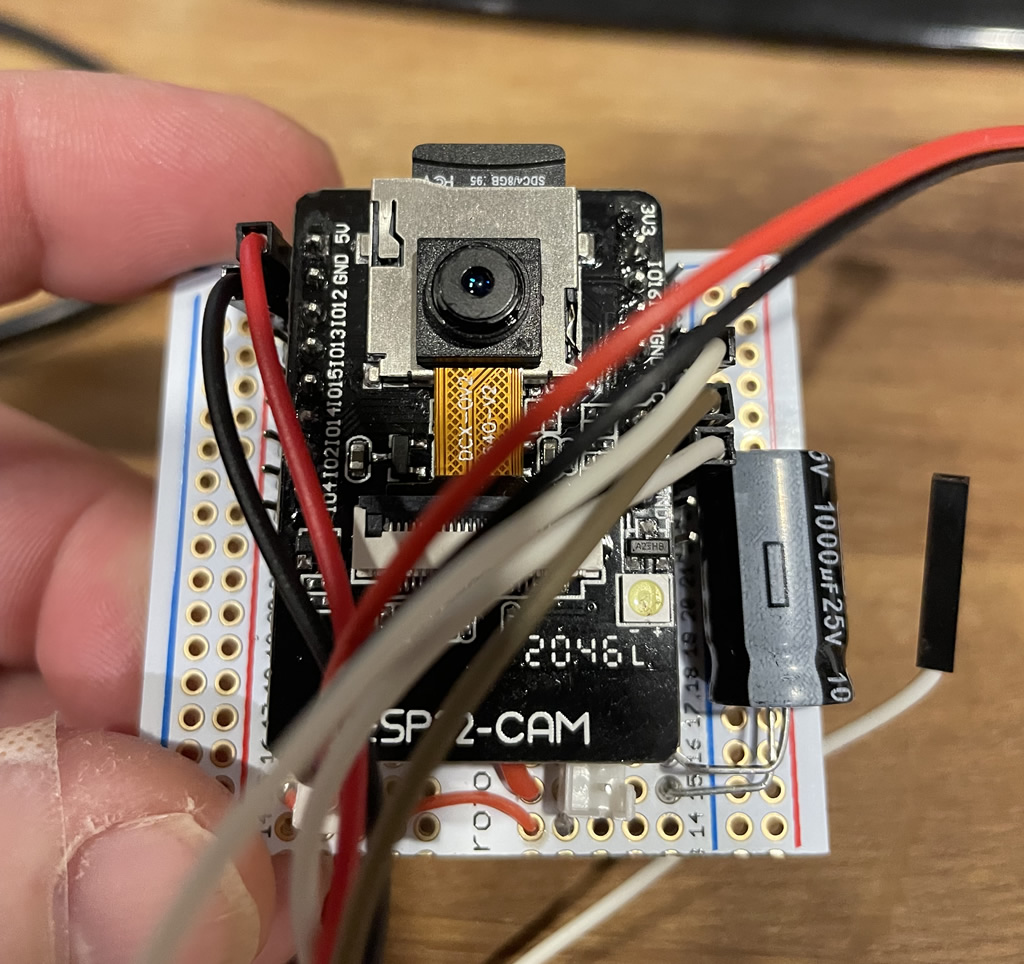
I used an ESP 32 CAM MCU which comes equipped with an OV2640 camera, WiFi, Bluetooth, SD card and a built in LED – which is great as all these components were necessary. The only other addition aside from wires, connectors and a cap is a photoresistor (LDR) sensor. It should work on most any resin printer as most are based on the same technology – they use UV light to cure each layer. The light comes on, cures a layer, goes off, then the printer raises and lowers the print. Repeat. The ESP watches for changes in light (UV on/off) via the LDR sensor which translates to a voltage change which is used to trigger taking a frame of the movie.
The LDR sensor is wired into the back of my Elegoo Mars Ultra 4K resin printer. It’s non-intrusive in that it’s not tied into the printer’s main board or other electronics. It simply mounts internally and faces the area where UV LEDs illuminate upward onto the LCD screen. The sensor readings can be tweaked to determine “dark” vs “light”, so even if there is some ambient light near the sensor, that can be scrubbed out.
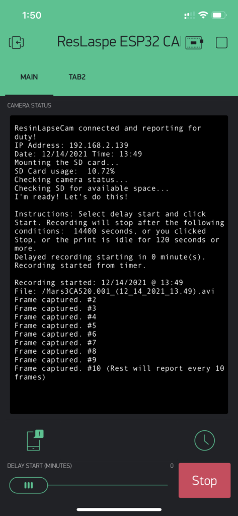
Hardware is composed of an LDR sensor (watches the printer UV light) and the ESP32 CAM which does the bulk of the lifting (AVI movie creation, watching timers, frame capture and movie completion as well as the rest of the computing work). It also uses the Blynk app (phone) as a HMI interface to show status updates via the terminal window, start/stop, frame status, and also has a delay slider to delay recording start by a selected # of minutes. This is needed as the first ~100 layers can’t be seen due to the height of the resin bed lip.
When a recording is started the ESP checks the SD card, creates an AVI file to start dumping frames into, captures frames while in operation, then processes and closes the AVI into a proper time-lapse movie when the recording has stopped.
Features:
- Records time-lapse AVI movies to the SD card
- The app controls logging, start/stop, frame status , and also has a delay slider to delay start recording by x minutes.
- The ESP has a number of features as well including a timer watch that triggers after 120 seconds of inactivity. The assumption is the print is done (no more UV light on/off cycles) and trigger the recording to stop and to complete the movie
- I also added a feature to view stills via web-browser on my phone. This allows me to ensure the camera is pointed at the right spot as well as adjust environment variables such as lighting. Initially I had used a live streaming option but it bogged the ESP down too much, so I reverted to this method (take picture and view). Key is it works.
The Good / The Bad:
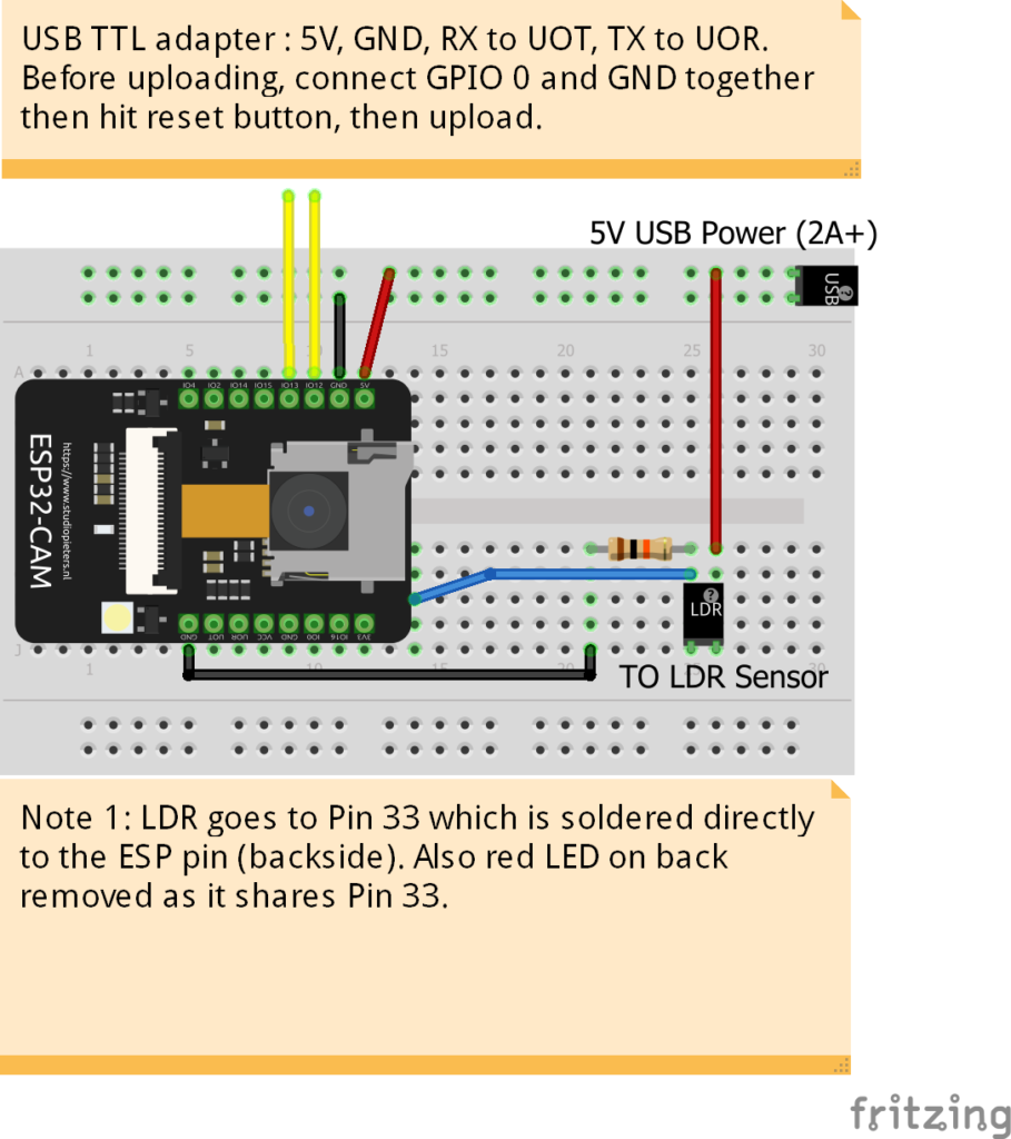
Pins pins pins!!! The ESP32 cam is a great little unit but the built-in SD/Camera/LEDs etc take up all the available pins. Which left nothing to use for the LDR. To solve this I had to get creative. The tiny red on-board LED was not needed, and it’s on Pin 33. So, simply de-soldering the resistor nearby it opens up Pin 33 for the LDR. I had to solder a wire directly to the ESP32 mainboard pin 33 and ran that to the LDR. So, to do this, you will need to do some surgery, but it’s pretty easy!
Components / BOM:
- ESP 32 CAM MCU. Note: It doesn’t have USB for loading sketches, so don’t forget to add a TTL adapter, or buy both together (link above)
- LDR Photoresistors (suggest getting > 1)
- You’ll also want a breadboard, headers, connectors and wiring. I use Banggood and suggest checking there as they have most of this stuff.
- If you are looking for a resin printer, check some out here.
- Don’t forget a good USB power supply (2 Amps should do). In this case, it’s not using the USB connector, but instead a separate connector wired to the 5V in with a 1000uF capacitor in parallels to stabilize power demand.
- Full disclosure, I get a small referral fee if you buy from the above links. You don’t pay any more, but a fraction goes to me to help support my projects.
The hardware build is pretty much straight forward. Power is provided from a 5V USB cable. This drives the ESP and the LDR. The LDR is wired to 5V, GND and data pin 33 with a 10K resistor across the data pin and GND. Because the ESP32 CAM was so thin on available pins, I had to hack out the red LED on the back (not needed) and directly solder to pin 33 on the ESP board itself (not shown in the picture). I had hoped not to do this bit all other pins were used by either the camera or SD card. I also wired connections in to RX/TX/5V/GND for future firmware updates. I had thought about using OTA but think there would have been issues due to the demand on processing etc. Note: I also added a 1000uF cap to smooth out power (not shown below, but in other pictures).
The Code:
Your Support is Appreciated: A lot of time is put into designing and building my projects, as well as the creation and editing of these build logs and videos. If you find them useful, please consider a small donation, or buy me a coffee. It will go to purchasing new items/components for future projects and help support the work I do here. You can support me either via Ko-Fi or PayPal below. Additionally, clicking the above product/part links also helps and it costs you nothing. Thanks!
Disclaimer: Although this has been tested extensively, assume that it’s not free from defects/bugs etc. No assumption of warranty should be taken, and you accept any / all risks that come with building your own version and any outcome that may arise from that. Per the licensing agreements you must retain credits and related info at the top including reference to this blog.
Usage & Code: Please see my Disclaimer page.
Controller App (Blynk) 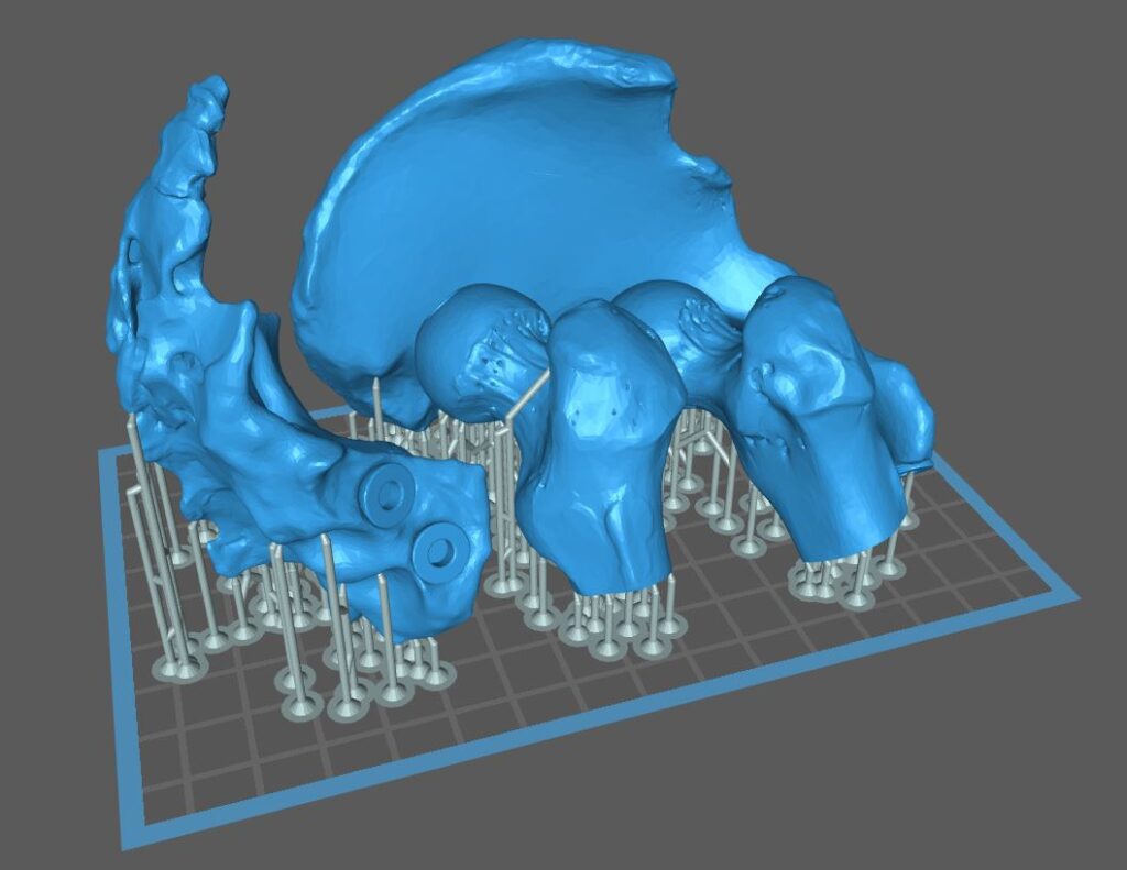
Print Sample 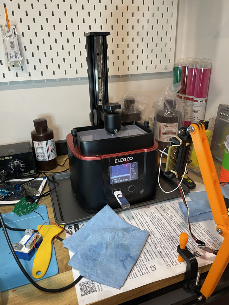
Testing Testing


Comments: