I’ve got a lot of stuff in my garage, and having 3 kids (one of them being me!) with forgetful minds, the garage door is sometimes left open over night. I don’t really like that sinking feeling after waking up the next day to find the door was left open. Between loosing valuables and critters that make a mess of garbage, I finally decided it’s time to take a stance! I have an IP Cam mounted inside the garage and, for the past few years, have used it as a means to monitor valuables. I wanted to take it to the next step by getting notifications of door status both inside my house (blinking LED in the hallway I could check before bed time) and on my various smart devices (iOs/Android). I also wanted to be able to remotely open/close the doors as well as do away with the keycode entry system I have, and instead use a fingerprint scanner to open/close the doors. (I’m good at scope creep). During my daytime job I spend much of my time managing it, and, in my hobbies, loosing control of it! It’s my style, what can I say. This is now integrated into my WIoT-2 master unit.
<!–more–>
What it Does:
Monitors both garage doors identifies status via:
LED that blinks inside the house (to alert us before we go to bed)
iOS / Android Blynk App for notifications and remote control of doors.
Allow open / closing of either garage door by:
Simple buttons on the controller itself inside the garage (Allows the garage to be closed from inside without needing to enter a code).
Fingerprint sensor mounted on the outside of the garage.
Remotely using the Blynk app on Android or iOS devices.
Includes Patented MeagerSecure password encryption. 😉
Uses Arduino and IOT connected components to web-enable the hardware.
How it works:
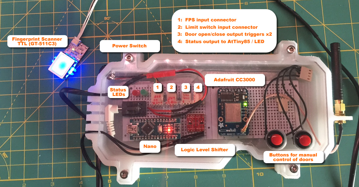
The project takes a number of features of the garage openers that are already in place. I pulled additional lines from each opener that are uses for the manual opener buttons already located in the garage. These are connected to 2 relays in the controller and triggerd by Blynk or the fingerprint scanner. I also added to limit switches to each door. The circuit is closed when a door is fully open and open when the door closes. These are used to feed status to the Open? LED’s in Blynk. Wires for the open/close, limit switches and remote LED monitors all run into the enclosure.
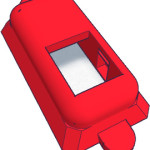
3D printed enclosure for the fingerprint scanner module and remote LED monitor.
5V 1A power supply
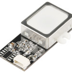
Fingerprint Scanner:
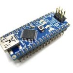
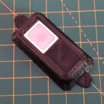
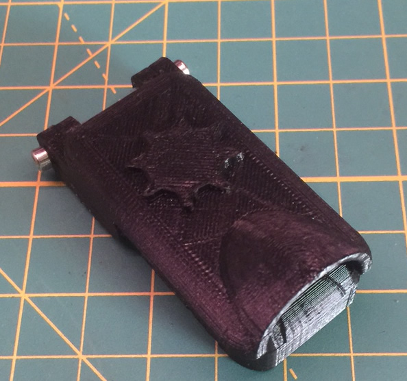
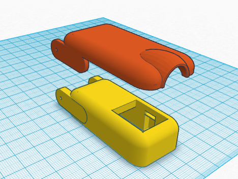
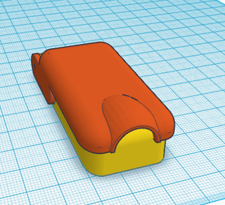
The fingerprint scanner is going to be mounted outside in the elements. Many hours were spent on Tinkercad designing an enclosure that would shelter the unit from the elements while still providing ease of access. I also decided to take a gamble and try waterproofing the fingerprint scanner board. After doing some research I came across NeverWet. Although Rustoleum does not recommend it be used on electronics, it seems many people have tried with success, so I decided to roll the dice. I decided to first try it on a spare Nano I had laying around. After it was complete, I did the water dunk test and it worked fine. It leaves a milky residue layer over everything. I did some testing to see if the layer provided any conductivity which would be bad news – but did not detect any. Afterwards, I took a chance on the Fingerprint Scanner, which also worked. I’m still toying around with designs on the enclosure. Primarily to come up with something that provides better shelter from the elements. As for functionality, the FPS allows for enrolment of up to 200 finger scans, so I can do the whole family.Latest Design: Allows for a cover to protect the unit and will open/close on its own:
Remote Control via iOS / Android:
I am using Blynk to remotely monitor and control the garage doors. The picture over there>> is the iOS version. It’s a pretty slick app and approach. You can create buttons, sliders, graphs, LEDs and tag them to Analog, Digital or Virtual Pins on your Arduino. They can be on the sending or receiving end of state changes. The Analog and Digital pins match those pins on your Duino directly. The real benefit is in the Virtual pins. Blynk needs a method to assign actions to react, and uses Virtual Pins for this. The idea is you assign a Blynk button to a virtual pin, then use a subroutine within your sketch to intercept the state change (i.e from 0 to 1) and then write whatever code you want to react. In my case, when one of the door buttons are pressed, the function catches that, and triggers a door to open. I added a password-like feature by using 4 sliders. The concept is that you use each slider to identify a digit of a 4-digit password, then the app unlocks the buttons to open / close the doors for a period of time. The Arduino sketch actually takes care of this. The sliders will reset to 0 after a period of time. Additionally, a LED illuminates when the correct password was entered. Although it’s obvious that this whole approach is limited in security, it adds an additional level of obfuscation that does the trick for what I am trying to achieve here. As they say, it keeps the honest people honest.Blynk is relatively new and the developers are adding new functionality all the time. I have high hopes for the upcoming LCD widget. As my sketch has quickly approached the 32K limit, I will be looking to the LCD widget to offload some code responsibility to allow me to use the Blynk app to enrol new fingerprints to the scanner (amongst other things). I’ll be using the LCD widget to relay next step text while enrolling.
Pebble Time Notification:
Just got the latest iOS Blynk update and now can receive notifications on my Pebble Time when the hardware goes offline! Will also be adding open/closing notifications shortly.
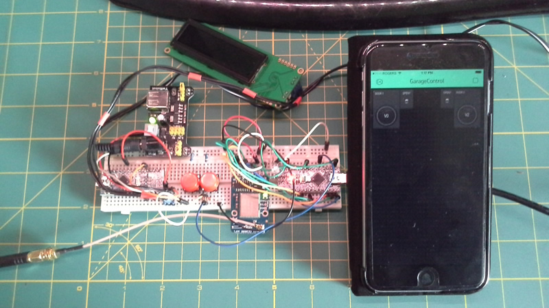
Prototyping phase:
Showing components hooked up via breadboard and the Blynk app customized with a few buttons and status LEDs. If you are looking for an easy way to get our device into the IOT world, you have to check out Blynk. It’s easy to setup and use. Took me less than 5 minutes to get it integrated into this project! The great thing about the app is that you simply download it, generate an Authorize token, open a sample Blynk app, add in the auth token and fire up the connection. Done. The sample apps provide enough examples to get you started with building your project.
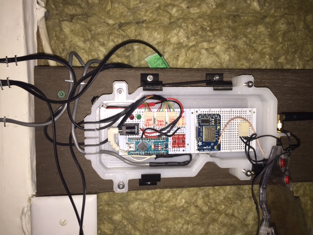
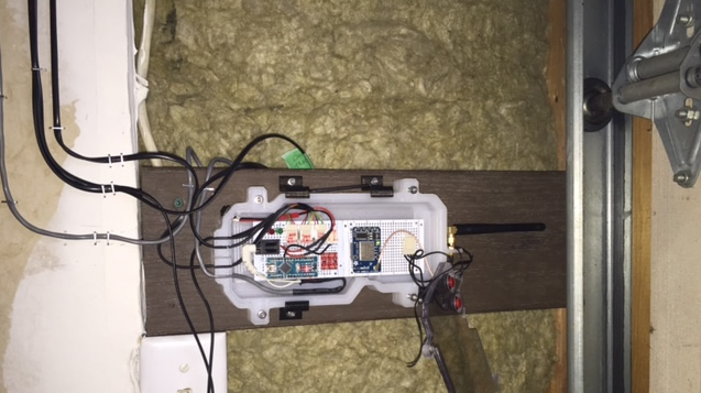
Final Control Board & Custom Enclosure with FPS ready for install:
This was one of my bigger projects as it contained many components and spanned both local control and the Internet via smartphone. The enclosure was custom milled out of a single cutting board. One of the biggest challenges I had was issues with the Nano / CC3000 freezing and locking up. This not good as it required a physical power cycle. This thing sat mostly complete on my desk for 2 weeks while I tried to figure out how to solve the issue. I also used this as debugging time to see how long it would remain running. Now that I have fixed the crashing issue, it has been running non-stope for days now. More on that below.
Items of Interest:
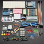
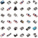
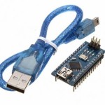
UNO R3 + Touch ScreenStarter Kit37 In 1 Sensor KitNano (ATmega328P)Uno ATmega16U2Uno R3 Advanced KitHC-06 Bluetooth
The Nano/CC3000 crashed about once per day. The controller would lock up and could not be recovered without physically powering cycling the controller. To deal with the issue I tried a few different methods:
CC3000 Catch:Catch the CC3000 by checking it’s connection state and re-initiating it. This did not work as the crash was at the Nano level (I used a blinking LED for a heartbeat – which always stopped.
Software Reset:Added a software reset routing based on a timer (about every 5 minutes) and a digital pin wired to RESET. This did work to reset the Duino, but it did not catch the issue when the controller crashed. The loop simply stopped running.
Watchdog Timer:I then stumbled across the built-in Watchdog timer (AVR WDT) I landed on this simple method (other options here). However, using a Nano clone, I ran into some snags. Turns out that these clones use some base bootloader that has certain default features. Namely, when the Watchdog catches a fault and triggers the Nano to restart, it goes into an endless bootloop (see tips below how to fix this). The fix. I stumbled across Optiboot and followed the steps to install it. However, I ran across another issue – the boards did not show up in Arduino IDE 1.6.4, so I opened 1.0.5, followed the steps to add the Optiboot there. Then, selected the Nano / Due… 328p Optiboot in the Boards menu. re-complied the code with the WDT settings added, downloaded and voila! It works. I left the controller on overnight and it’s still ticking along. I presume it has done at least 1 restart since. The code is as simple as:
#include <avr/wdt.h> – add this to the include section.
wdt_enable(WDTO_8S); – I used the 8 second option, but there are many choices. You will want to make sure that the WDT is only enabled after any start-up routines are done. Mine weas placed at the end of Setup(). For example, I am using the Adafruit CC3000 which needs to establish a connection to WiFi in the Setup routine. I added this after that call completes.
wdt_reset(); – Then, all you have to do is put the reset call in your main loop. A good idea is to put it at the beginning. If you have sub-routines that may take more than 8 seconds to complete their task, you will also want to add this call within them. The idea here is that these are normal operations for your code, and all you are doing is telling the Watchdog Timer to NOT restart the Arduino by resetting the timer back to 0 seconds. If your Duino should crash, the Watchdog Timer is running as a separate process and continues running. It will no longer see the reset call and trigger the Duino to restart. Also it is important to note that this does not trigger the reset of peripherals connected to your Duino. If you need that, you may want to use a digital pin that goes HIGH to trigger some sort of relay or transistor to turn on the peripherals. That way, when the Nano resets, you can bring that pin LOW, then HIGH when the code restarts.
Reality vs Prototyping:
It never fails… Try as best as possible to re-create a similar environment to what it would be like in the garage, I ran into a few issues.
WiFi Signal: I suspected this would be an issue and it was. The controller is mounted at the front of the garage interior. It has to go through a fair bit of concrete to reach my router in the basement. I had started with a stubby antenna and, although it connected, it seems the signal was too weak. Luckily I had a longer antenna and swapped them out. I still have some concerns as the connection is more flaky as my kids get on their iPads and eat up some of the bandwidth.
Door Limits: This one completely caught me off guard. It was one of the simpler components of the system. Each door has a limit switch attached to it. If a door is open, the switch is closed and thus I can do a simple continuity check on the pins for each door. In code, I had a simple check for 4 states. When one door is open, I check as follows ( if ((d1LimVal >= 1000) && (d2LimVal == 0))). What I found was that although the open door (> 1000) evaluate to be true, the open door did not. During testing, with the limit NOT tripped, the value was 0. However, when wires were all connected, I the 2nd value was seeing numbers between 2-6. A simple adjustment to the sketched fixed it, but I was not expecting this.
Something else to keep in mind. No matter how well you plan, you are likely to screw up pin or variable assignments. What I am getting at here is I have 2 doors. They both need to be monitored, they both need to have a physical switch, and also be connected to relays. That’s 6 places to screw up. The great advantage of the config this can be easily remedied during installation by swapping variables or pin assignments after everything is hooked up. The only (minor) glitch I ran into is the 2 physical door opener switches had no software component and I wired them up wrong to the 2 relays. A simple swap of the pins in the connector did the trick.
Other Thoughts:
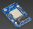
Could use an ESP8266 or similar WiFi-enabled device. I have an Adafruit Huzzah that I wanted to try, but it came too late in the project phase. Given the CC3000 is a bit flaky, I may switch out to the Huzzah at some point in the future. Unless of course there’s code out there to detect and reset the CC3000 when it freezes.
Pebble Time integration – Now that I have my Pebble Time, I’d like to see the Blynk app send notificaitons to it, and be able to trigger responses (i.e. Open / Close a door). If I get more free time, I might venture to develop an app for this myself.
Tips:
Watchdog Bootloop: If you were toying around with the AVR Watchdog and discovered (as I did) that you have a Duino who’s bootloader does not play well with the Watchdog, you will want to follow the steps I noted above to install the Optiboot bootloader. Here’s a tip to get your Duino working again. Remove all power from the Nano / project. Plug the USB into your PC, comment out the offending watchdog lines of code (namely the wdt_enable(xxxxxx) statement), re-download the sketch. Note, in some Nano’s, you have to click the reset button the moment the IDE starts uploading.
I also have an IP Cam in the garage. I’m hopeful the Blynk folks will consider adding a viewer widget to allow me to plop timed stills of my IPCam in the app. The concept here is the status LED’s would tell me if doors are opened and when they are closing, but it is always nice to see that I’m not going to close the door on a car that is half parked in the garage. Worst case situation, I can open my IP Cam app separately and look at the IP view before triggering a door to close.
Christian Hilton -January 14th, 2019 at 10:45 pmnone
Comment author #17657 on IoT Garage Door Monitor/Opener with Finger Print Scanner by PlastiBots
I have a similar project I could do to more earnestly start looking into, it is for gate security and needs to include a closing mechanism with it as there’s no existing motor or tech to speak of…, these are hinged wooden gates though, quite heavy so hoping just to unlatch a sprung hinge or door closer and let physics naturally do the rest – but it will still require off-grid power to trigger this mechanism and then also slide a shoot bolt into place to lock it, and to be able to supply a charge for that [battery] from solar panel replenishment, while adding light sensing & real time clock cross-referenced ways to set it off, have all started to make it into something beyond a starter project, and it will certainly mean changing aspects of the gate so there’s a new inset door for pedestrian access whereby the activated shoot bolt keeping it closed can be manually open from within.
I think the trick is just to get it closing, then sensing it is closed triggering the shoot bolt that locks it shut, providing the inset door is finished first [which can be a completely separate project and include the shoot bolt providing there’s scope to add the electronic means of controlling the shoot bolt later]…
…It has not been easy just looking into it, I’ve posted on the subject a few times and downloaded software for designing electronics, ultimately only making very slow progress in a learn as you go approach – any pointers?
Dave-January 16th, 2019 at 8:32 pmnone
Comment author #17658 on IoT Garage Door Monitor/Opener with Finger Print Scanner by PlastiBots
Hmm… Interesting. Working with things that are imperfect (gate) that are affected by seasonal changes is risky. It may work when you install it and completely fail when it’s cold months later. I’ve not taken on something like this so not sure what to suggest. I agree that you should let a spring/gravity do the closing. The trick will be how you engage some sort of locking mech.

 the garage door is sometimes left open over night. I don’t really like that sinking feeling after waking up the next day to find the door was left open. Between loosing valuables and critters that make a mess of garbage, I finally decided it’s time to take a stance! I have an IP Cam mounted inside the garage and, for the past few years, have used it as a means to monitor valuables. I wanted to take it to the next step by getting notifications of door status both inside my house (blinking LED in the hallway I could check before bed time) and on my various smart devices (iOs/Android). I also wanted to be able to remotely open/close the doors as well as do away with the keycode entry system I have, and instead use a fingerprint scanner to open/close the doors. (I’m good at scope creep). During my daytime job I spend much of my time managing it, and, in my hobbies, loosing control of it! It’s my style, what can I say. This is now integrated into my WIoT-2 master unit.
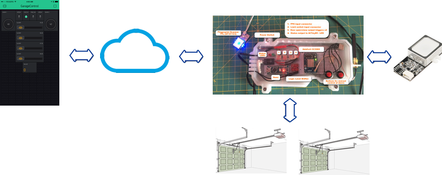

 Many hours were spent on Tinkercad designing an enclosure that would shelter the unit from the elements while still providing ease of access. I also decided to take a gamble and try waterproofing the fingerprint scanner board. After doing some research I came across NeverWet. Although Rustoleum does not recommend it be used on electronics, it seems many people have tried with success, so I decided to roll the dice. I decided to first try it on a spare Nano I had laying around. After it was complete, I did the water dunk test and it worked fine. It leaves a milky residue layer over everything. I did some testing to see if the layer provided any conductivity which would be bad news – but did not detect any. Afterwards, I took a chance on the Fingerprint Scanner, which also worked. I’m still toying around with designs on the enclosure. Primarily to come up with something that provides better shelter from the elements. As for functionality, the FPS allows for enrolment of up to 200 finger scans, so I can do the whole family.Latest Design: Allows for a cover to protect the unit and will open/close on its own:
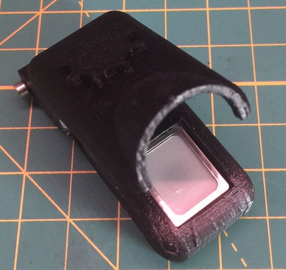
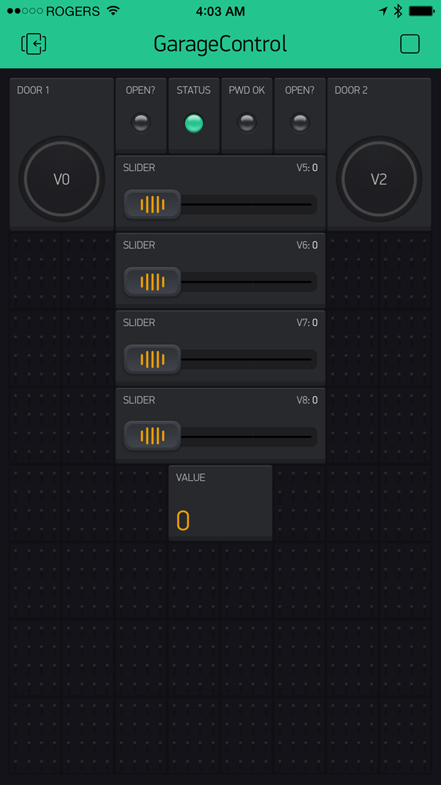 buttons, sliders, graphs, LEDs and tag them to Analog, Digital or Virtual Pins on your Arduino. They can be on the sending or receiving end of state changes. The Analog and Digital pins match those pins on your Duino directly. The real benefit is in the Virtual pins. Blynk needs a method to assign actions to react, and uses Virtual Pins for this. The idea is you assign a Blynk button to a virtual pin, then use a subroutine within your sketch to intercept the state change (i.e from 0 to 1) and then write whatever code you want to react. In my case, when one of the door buttons are pressed, the function catches that, and triggers a door to open. I added a password-like feature by using 4 sliders. The concept is that you use each slider to identify a digit of a 4-digit password, then the app unlocks the buttons to open / close the doors for a period of time. The Arduino sketch actually takes care of this. The sliders will reset to 0 after a period of time. Additionally, a LED illuminates when the correct password was entered. Although it’s obvious that this whole approach is limited in security, it adds an additional level of obfuscation that does the trick for what I am trying to achieve here. As they say, it keeps the honest people honest.Blynk is relatively new and the developers are adding new functionality all the time. I have high hopes for the upcoming LCD widget. As my sketch ha
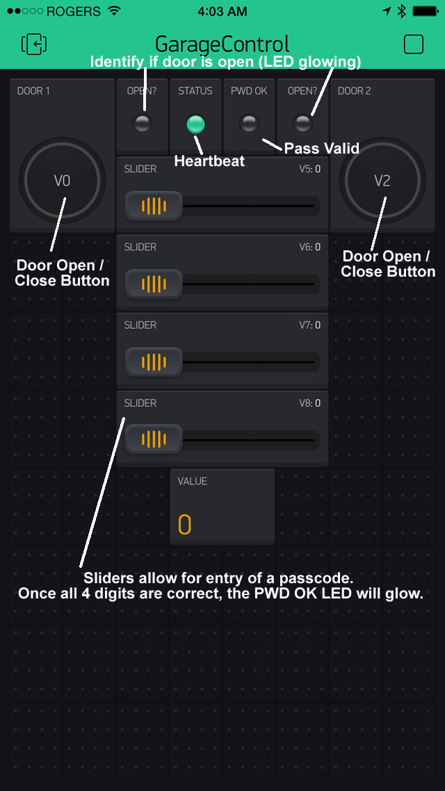 s quickly approached the 32K limit, I will be looking to the LCD widget to offload some code responsibility to allow me to use the Blynk app to enrol new fingerprints to the scanner (amongst other things). I’ll be using the LCD widget to relay next step text while enrolling.
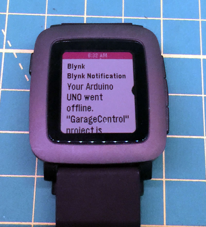
 If you are looking for an easy way to get our device into the IOT world, you have to check out Blynk. It’s easy to setup and use. Took me less than 5 minutes to get it integrated into this project! The great thing about the app is that you simply download it, generate an Authorize token, open a sample Blynk app, add in the auth token and fire up the connection. Done. The sample apps provide enough examples to get you started with building your project.
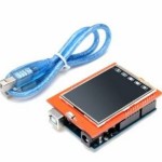

 – Android App to Control Robots")
Any plans on sharing some of your code for this project?
Done. Thx for the reminder as I had been meaning to upload the sketch.
Thanks. Great post. Going to attempt to create something like this.
I have a similar project I could do to more earnestly start looking into, it is for gate security and needs to include a closing mechanism with it as there’s no existing motor or tech to speak of…, these are hinged wooden gates though, quite heavy so hoping just to unlatch a sprung hinge or door closer and let physics naturally do the rest – but it will still require off-grid power to trigger this mechanism and then also slide a shoot bolt into place to lock it, and to be able to supply a charge for that [battery] from solar panel replenishment, while adding light sensing & real time clock cross-referenced ways to set it off, have all started to make it into something beyond a starter project, and it will certainly mean changing aspects of the gate so there’s a new inset door for pedestrian access whereby the activated shoot bolt keeping it closed can be manually open from within.
I think the trick is just to get it closing, then sensing it is closed triggering the shoot bolt that locks it shut, providing the inset door is finished first [which can be a completely separate project and include the shoot bolt providing there’s scope to add the electronic means of controlling the shoot bolt later]…
…It has not been easy just looking into it, I’ve posted on the subject a few times and downloaded software for designing electronics, ultimately only making very slow progress in a learn as you go approach – any pointers?
Hmm… Interesting. Working with things that are imperfect (gate) that are affected by seasonal changes is risky. It may work when you install it and completely fail when it’s cold months later. I’ve not taken on something like this so not sure what to suggest. I agree that you should let a spring/gravity do the closing. The trick will be how you engage some sort of locking mech.