
DynaTrax
December 2006:
Sometimes my robot building ideas are spurred by nothing more than wanting to make use of one or more cool items that I get from time-to-time. In this case it’s two – tread tracks that can be had if you own the Technic Snowmobile (8272) and a TechnoStuff Tilt/Accel Sensor. 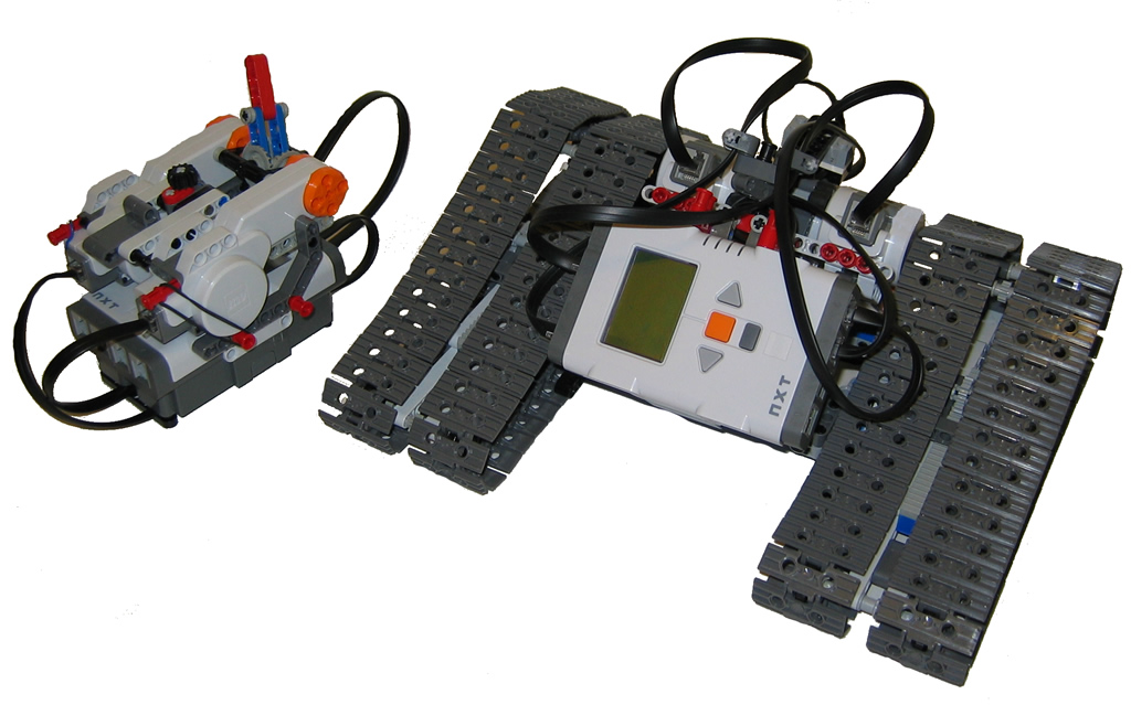 I was fortunate to have received a huge bag (a few hundred segments along with wheels) of the new tread tracks a while back and begun playing with them to see how they compare to their smaller black Technic counterparts. In a nutshell, I like these ones better as they are larger (more suited to the size of robots and Technic creations I build) and stronger – they dont come apart as easy. They also have pin holes in them to boot, so the sky is the limit for making large tracked vehicles.
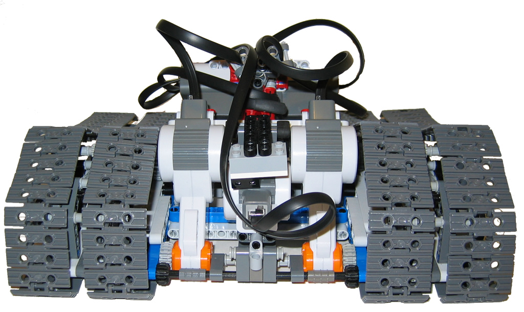
Anyway, enough of that. So, what is DyanTrax? I wanted to take advantage of the tilt sensor and use it to detect when a vehicle needed to stabilize itself in situations such as climbing a hill. DynaTrax is able to expand or contract the tread base so that there is more or or less surface area touching the ground (reads more grip) as well as spreads its center of weight to give it more stability. The following pictures show DynaTrax with the tracks in normal and expanded driving modes.
Some highlights of its features:
- 2 NXT’s
- Bluetooth for remote communications.
- Remote has 3 channels (left/right, fwd/rev, expand/contract the tracks)
- Can be switched to auto mode for the track expansion using feedback from the Tilt Sensor.
- 6 Motors (3 to drive and 3 as rotation sensors on the remote)
[ad name=”GoogleAS728x90″]
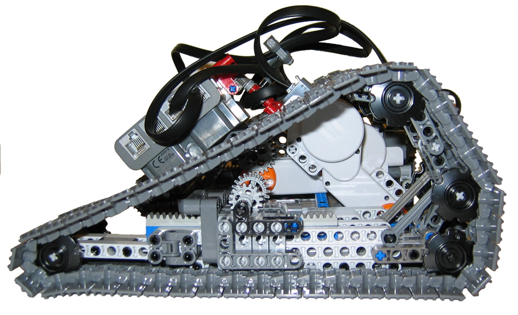
The following shows DynaTrax in resting mode. The track slider is at its middle point. Click pic for larger image. 
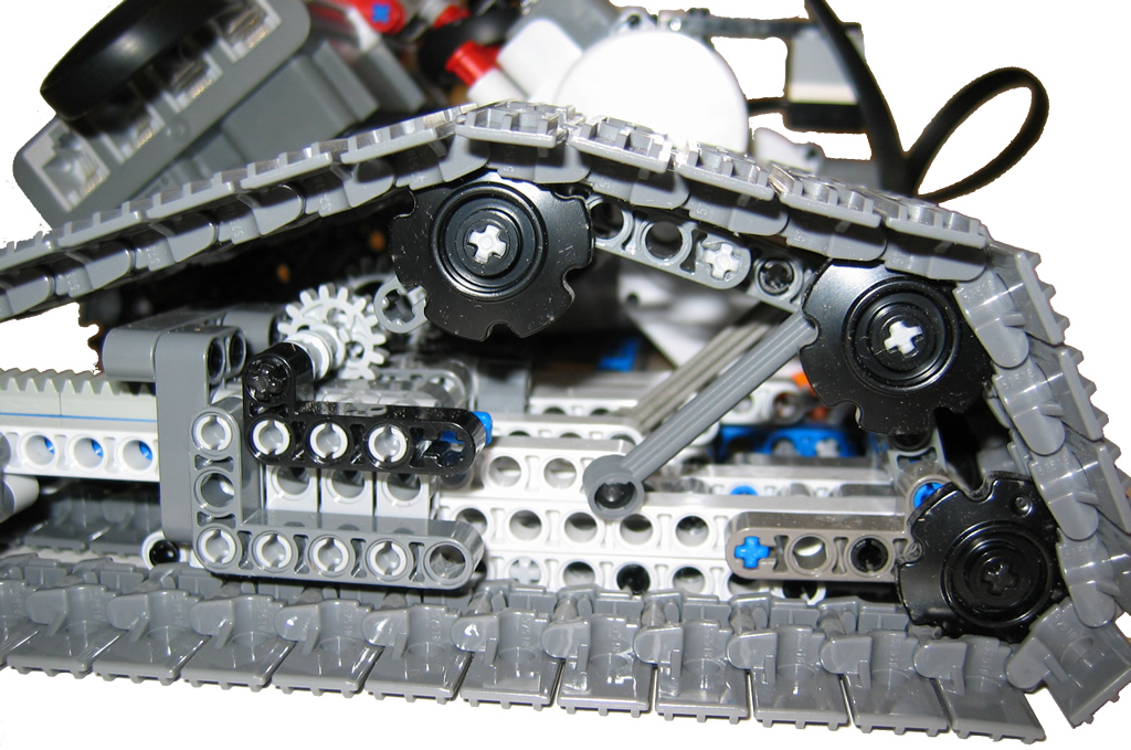
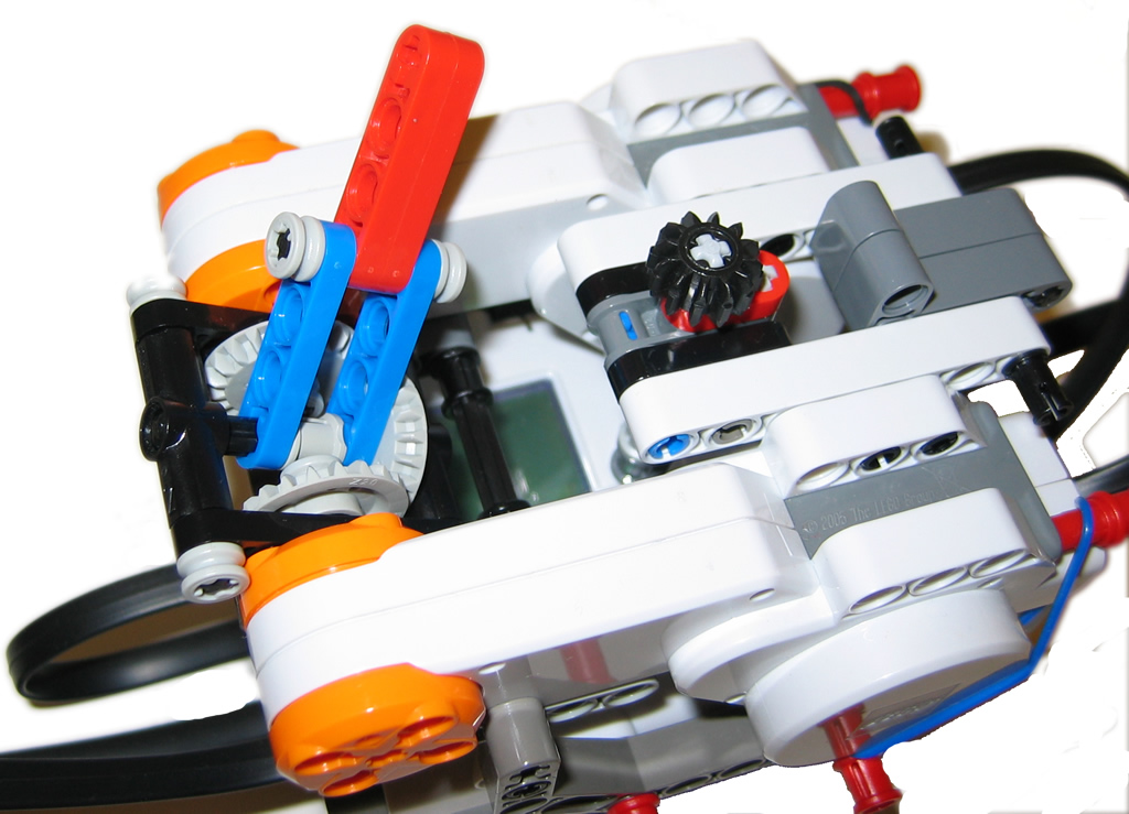
A close-up of the track drive in expanded mode. In this mode, a central motor kicks in to expand the tracks and lengthen the wheelbase. The arm you see here is linked to the slider that expands the tread base. At the same time, the arm lowers which allows for the top wheel to move down and the tracks expand. It was difficult to get this right as the geometry of the tracks had to be consistent as it goes from drive mode to expanded mode. Getting it right was a matter of playing with different length beams, angles and connecting points until the path was just right. Although not perfect, what I now have is quite effective. Click for a larger image.
Another close-up with the tracks in drive mode. The center of gravity is higher and the tracks are contracted.
[ad name=”GoogleAS728x90″]
The second NXT unit was used as a Bluetooth remote to control DynaTrax. It is using 3 motors as rotation sensors to take joystick movements and convert them into direction and speed for each of the 3 motors on DynaTrax. To do this in NXT-G, I used the following MyBlocks created by Brian Davis (thx Brian) to convert each of the remote motor’s direction and rotation values into direction and speed on DynaTrax.
The GetAngle block runs in the remote unit. Its job is to take the motor input and convert the value into a signed integer (eg -180 to + 180).
The PutAngle block runs on DynaTrax. Its job is to take the signed integer fed to it from the Bluetooth remote and convert it to a) direction (based on the signed value) and b) magitude (or speed) based on the number 0 – 180. These values are then fed to the drive motors to make DynaTrax move.
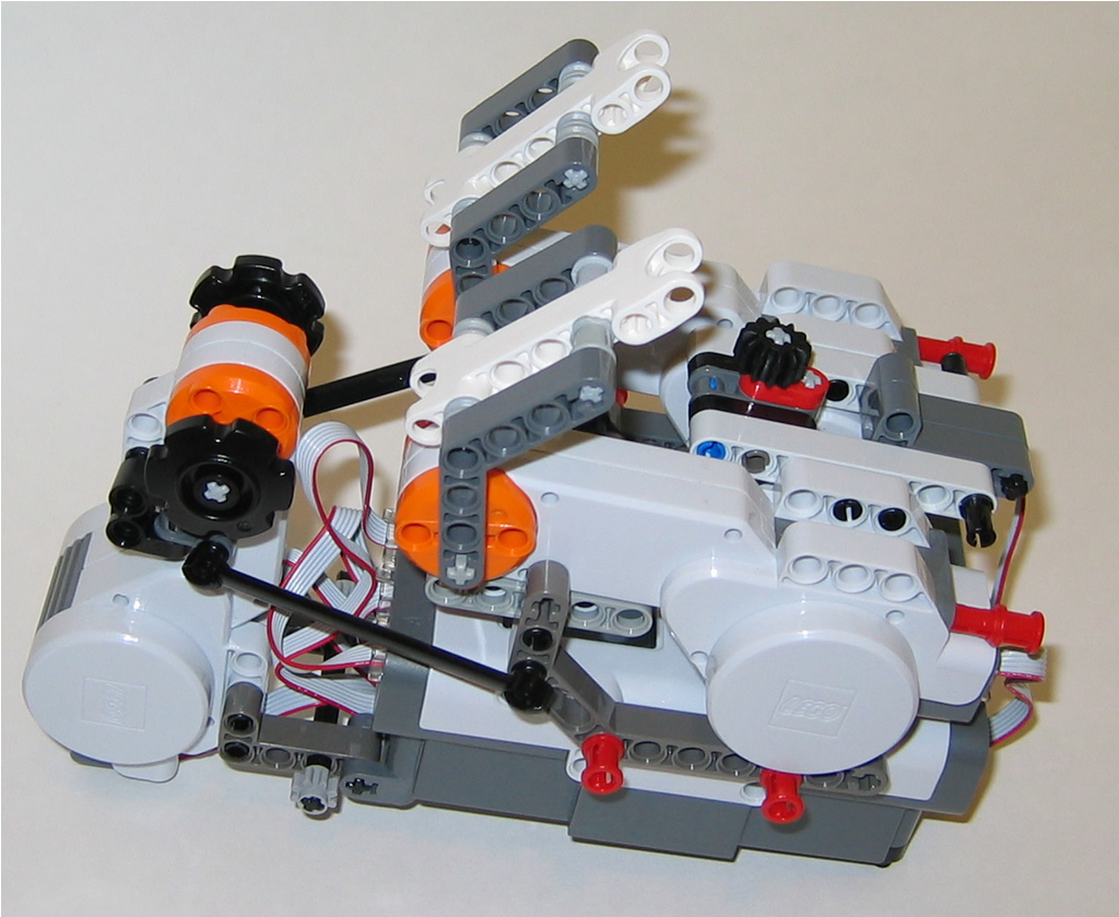
As for the remote’s configuration. I tried a few different prototypes. The one shown here uses gearing similar to that of a differential to integrate 2 motors to one joystick. I found that this method was not as good as seperate levers. I think this is partly due to the motors own friction which makes it harder to move he joystick arm freely. I finally settled on a dual level remote (shown below). This method worked best for this type of design.
Just a view from the back.
A tip for building strength into your robots – use the 90 degree connectors whereever possible. These things are great.

Alternate remote control configuration. This remote was used with a 3rd servor motor to control the track slider unit. I also mounted an axle that I could use to control the yellow button on the NXT. In the software, the button is used to reset the left and right steering levers to zero them out. This allowed me to reset the levers to a center position in case they got out of sync.
Have a look at the Mindsensor Flexi-Cables. I picked up a set of these cables and they work quite well. They are more easy to work with due to their being thin and more flexible than the stock ones.

This is a looking at the remote from the front.

Rate This Post: 
 (4 votes, average: 4.50 out of 5)
![]() Loading...
Loading...


Comments: