
BigWheel
Big Wheel (BW) was an experiment at building a robot that uses the HailFire Driod (StarWars) large wheels.  It’s job is simple; build an autonomous robot that can navigate any area while avoiding obstacles by not hitting them in the first place. To do this, BW uses a DIRPD sensor to “see” left, right and center. This allows BW avoide obstacles from 3 views before actually hitting them.
However, it is unable to avoid obstacles that are low (below the sight of the DIRPD sensor), and this is the reason for the dual touch sensors at the front. Read on for more details and information on some of its unique features… (click images for a larger view)
[ad name=”GoogleAS728x90″]
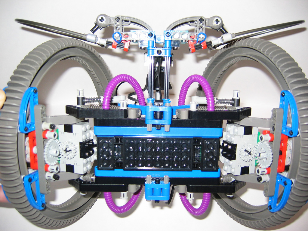
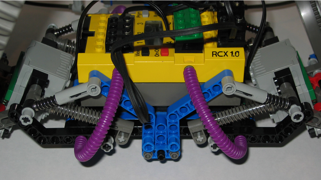
Side view of BW. The wheel mount and motor drive unit is the same for both sides. The system uses studless building techniques to make a light but sturdy system that holds together in tough situations. The stack of wire connectors shown on top of the RCX is used for the front sensors. There are 2 Cybermaster touch sensors used which are multiplexed to one sensor port. The port is set as LIGHT_SENSOR and values read are 1-1024. So, if the left sensor is touched the reading might be 224, right might be 776 and both might be 555. This allows 1 port and 2 sensors to provide feedback on left, center and right hits to the lower portion of BW. With this, BW can react accordingly.

The bottom of BW shows more detail on the drive system and sensor mounting mechanism. The drive system when through 3 revisions to get it right. The first few attempts were too bulky and not fast enough. This attempt got it pretty much right. The entire drive portion uses studless mounting techniques. It was tricky to get the motor to work in this system as these units still use the traditional approach for mounting (Lego if you are reading this – how about some holes in future motor designs?).
Each drive unit (wheel and motor mechanism) is completely independent of the main body and uses suspension to provide shock releif to the unit in the event of it having to climb or hitting walls etc.
In order to ensure that the balance was maintained, the bulk of the weight (RCX) was mounted below the center of gravity and to the center axis of the robot. But, the front sensor unit had to be mounted forward of this. The goal was to keep the unit as light as possible so that it would not cause the robot to drop forward while it was navigating. The current design worked well.
In the near future, I will be mounting 2 RC motors (the high speed ones). The challenge here will be to also accommodate a battery box (as these motors cannot be driven by the RCX).
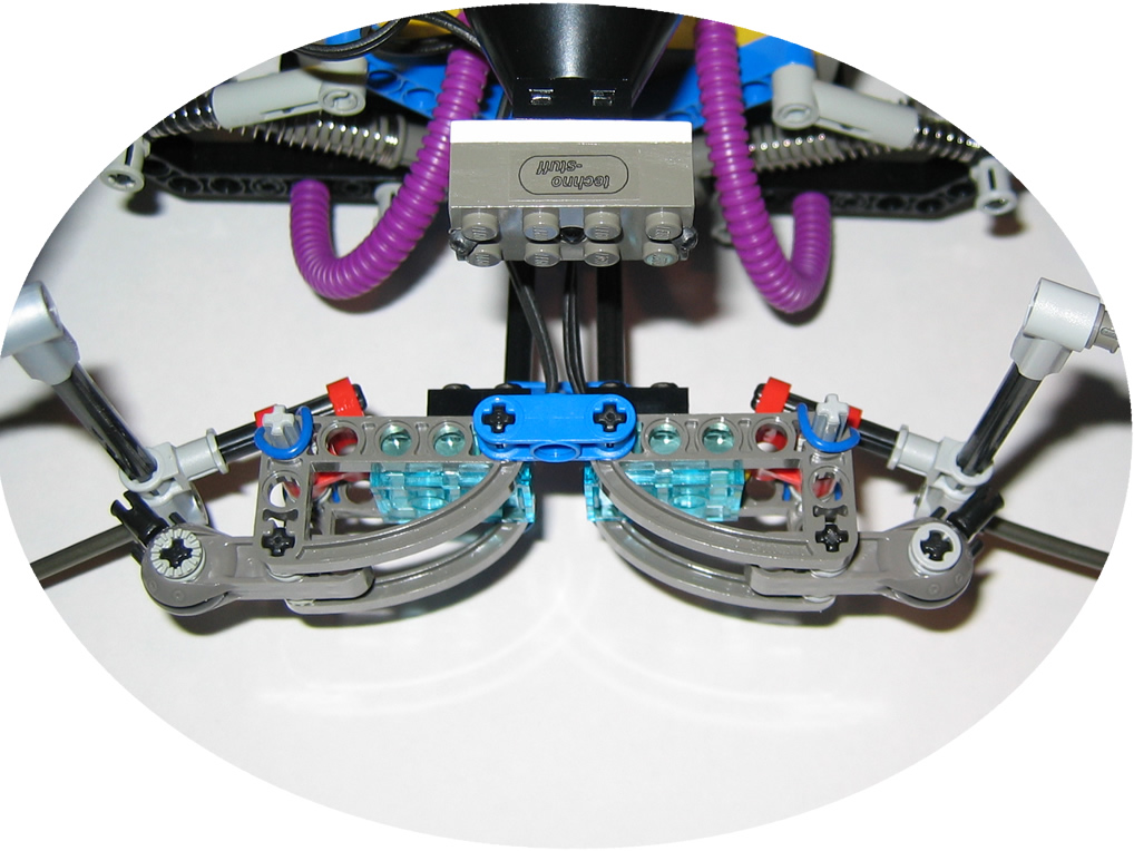
A front view of the main DIRP sensor detector. This is a fantastic sensor, built by Techno Stuff. I have also done a review of this sensor in my Reviews section. It detects left, center and right obstacles and allows a robot to actively avoid obstacles instead if hitting them first.
[ad name=”GoogleAS728x90″]
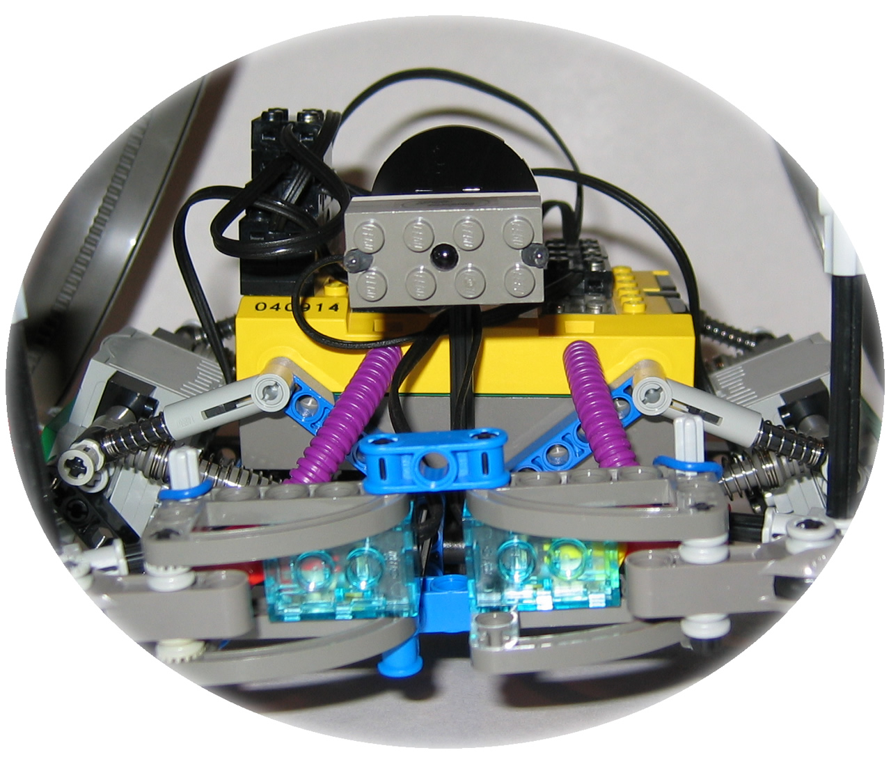
A top view of the DIRP and Cybermaster sensors. Together, they pretty much ensure that BW does not hit anything…
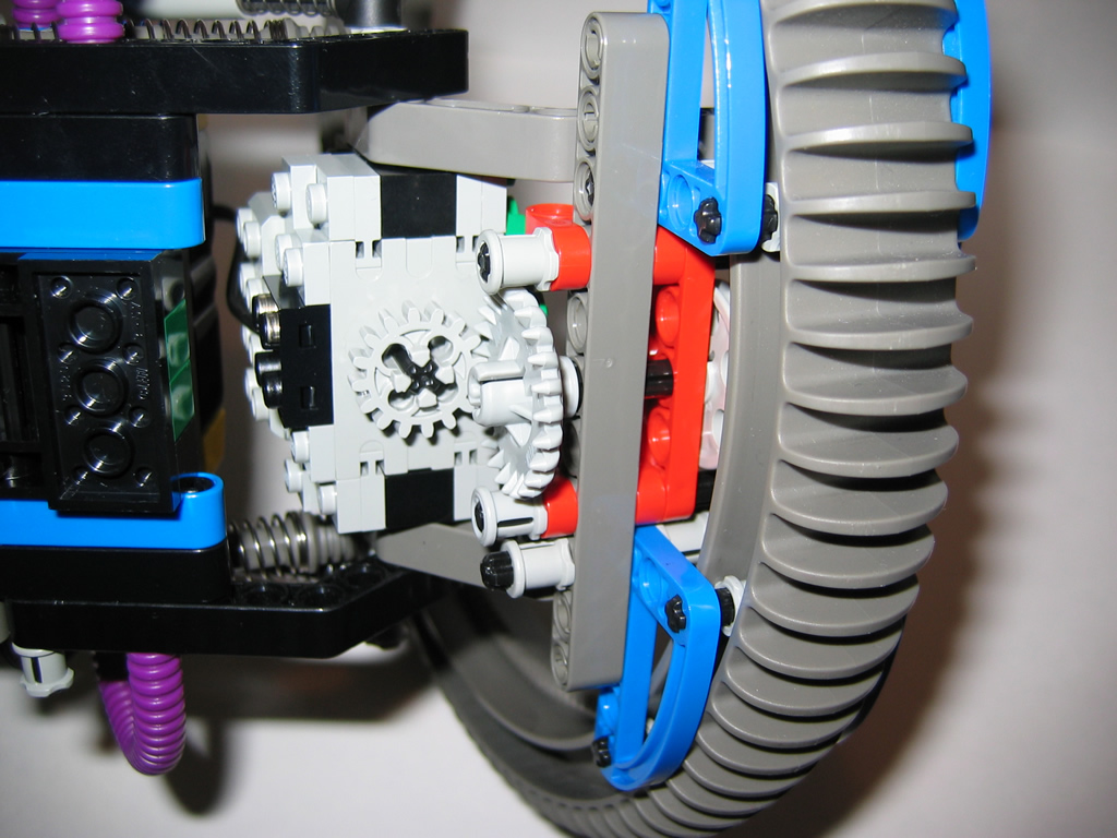
A close-up view of the drive mechanism from the top. The motors connects directly to a 24T gear which in turn drives the wheel unit.
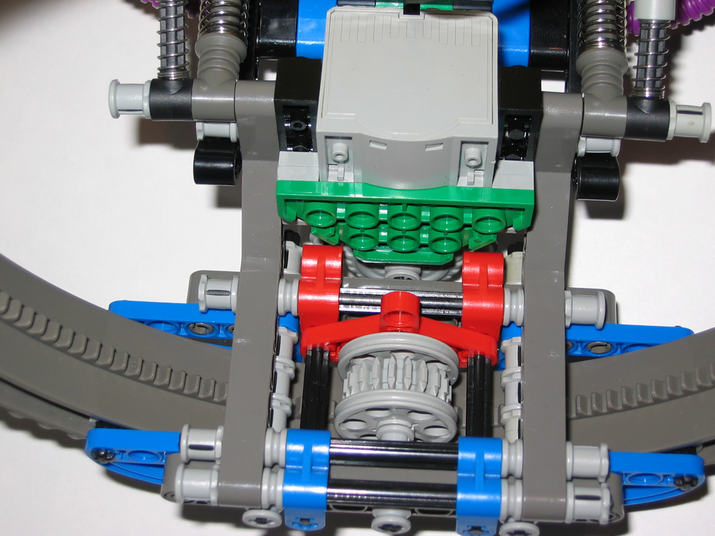
A bottom view shows the 16T motor gear and how it meshes with the 24T drive gear. The mounting is a floating system using studless technology.
The rear view shows the suspension used to provide float for BW. Both the front and rear have the same suspension setup. At first, I underestimated the weight of the robot and only used 4 shocks. It sunk right to the ground and both wheels hit each other (at the top). This improved design uses varying angles to trigger the suspension.
Rate this post: 

 (3 votes, average: 3.67 out of 5)
![]() Loading...
Loading...


Comments: