
PicoCam
PicoCam was built as a proof of concept. Its purpose was simple, navigate an area using typical avoidance routines while capturing live wireless video/audio and transmitting it to a receiver.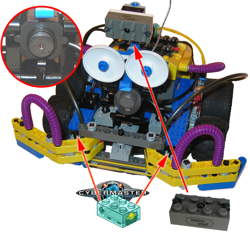 The was never really completed because I had other ideas brewing… The pictures shown here are of the final version, with working navigation, but I did not bother going the last step to get the live video to display (even though it will work).
PicoCam consists of a variety of sensors and other components. For navigation, the primary sensor is the DIRPD (grey) sensor mounted at the front (top). Setting this as SENSOR_TYPE_LIGHT in NQC allows it to provide readings for detection on the left, center and right sides. Most of the robots avoidance capibilities come from this sensor. It is able to avoid most objects with the exception of those that are low (it cannot “see” them). This is where the touch sensors come in. Their purpose is to allow the robot to react when the DIRP does not catch obstacles from the front, and when the robot backs into something from the back.
[ad name=”GoogleAS728x90″]

A close-up view of the DIRP light sensor showing the emitter and dual receivers.
PicoCam gets its name because of the tiny wireless camera that was mounted to it. This is one of those “spy / nanny” cams that you can get from pretty much anywhere – or Ebay… It is powered by a single 9V battery (does not last long) and transmits live colour video and audio to a receiver that can be plugged into a TV or computer (with the right video converter cabling). My original intention was simple – just build a robot that could navigate a room and transmit live video – providing a robot point of view. I never did test the camera on this robot because, soon after it was done, I started building the next…

A close-up view of the camera showing more detail on how it is mounted. It was pretty easy to fit it into the Lego standard dimensions.

This is a view from the top rear of the robot. It shows the rear Cybermaster touch sensor used to detect collisions from the back.

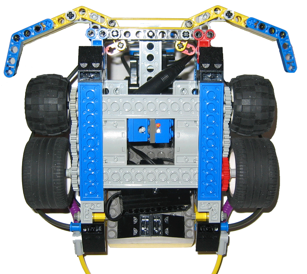
Picture of Cybermaster sensor from underneath. The sensor was wired to 1 port along with 2 other Cybermaster sensors. These sensors coded as Light sensors and values vary depending on which is engaged. By doing this, we can detect and react to all combinations (i.e. touch on FL + R, FR + R, FL + FR etc). This allows for great flexibility in programming responses to hitting obstacles.
[ad name=”GoogleAS728x90″]

A bottom view of the robot showing the line following light sensor. This activity was never programmed in code as I moved on to bigger and better things. The intent was to have to robot perform typical navigation routines and if it detected a line (black), it could start a line following routine.
Rate This Post: 
 (1 votes, average: 4.00 out of 5)
![]() Loading...
Loading...


Comments: