
Climber
Climber – One day while browsing the LEGO Mindstorms site, I noticed some pictures about a show in Germany. LEGO had built 2 cool wall climbing robots to help market the product. I was amazed at the design and capabilities that they had and wanted to find out just how hard it would be to build something like this and have it actually work. It was quite a challenge. Building the components was the easy part. Getting it to climb was (and still is) a challenge. The Climber has gone through another iteration as the one shown here is too heavy. To test the unit, I used a holesaw to cut 2 inch offset holes up a piece of wood plank. The idea would be that the Climber would start with one arm, pull itself up, and the the bottom part would shift. This would offset the Climber to one site and make it easier for the other arm to find a hole and pull itself up. This was to be a big challenge. Read on…
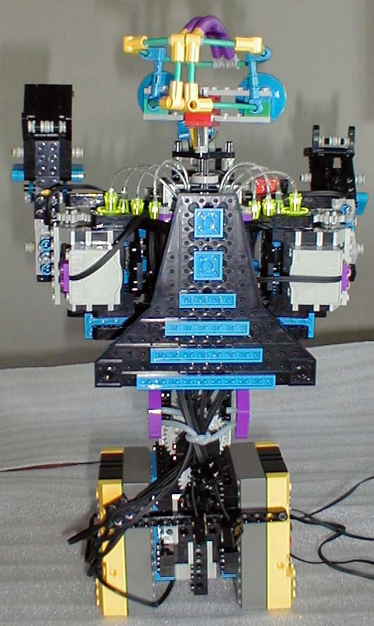
Showing the back of Climber. Features – the cam mechanism that turns the head can be seen at the top. One of the problems that I discovered after building it was that its design was correct in that it had the geometry to climb my test wall. The problem is that it is too heavy for itself. I should have called it Big Mama, cause it ain’t going nowhere but the bottom rung…
[ad name=”GoogleAS728x90″]
Outside pic of the left hand. One thing that I knew early on when building Climber was that its hands had to be built strong. I did this by using different techniques to get strength. I used a combination of beams and locking pins to secure moving parts together. Note the turntable. All axles were also reinforced by using friction spacers to ensure that while it is operating that stresses do not cause gears to slip, grind or come loose.
This angle again shows the use of reinforcements to strengthen the moveable parts. Climber was also designed to be modular. I wanted to make sure that each major part could be removed for repair/inspection with ease. This can be seen here by the mounts used to secure each arm to the torso of Climber. Attaching them were as simple as using 2 #12 axles to join the black inners to the main body.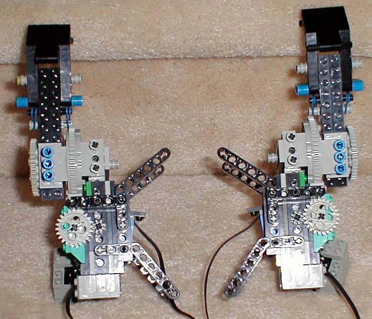
[ad name=”GoogleAS728x90″]
Top picture of the right hand. Another angle of the hand unit. This shows the touch sensor. The sensor was used to detect when the robot arm had reached its maximum “wrist” flexibility. Basically, as Climber would move up using an arm, the wrist area would pivot until it could not anymore. At this point, there was a lot of stress on the arm unit, and I wanted to know that via triggering a sensor.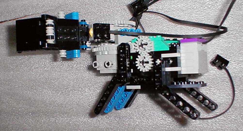
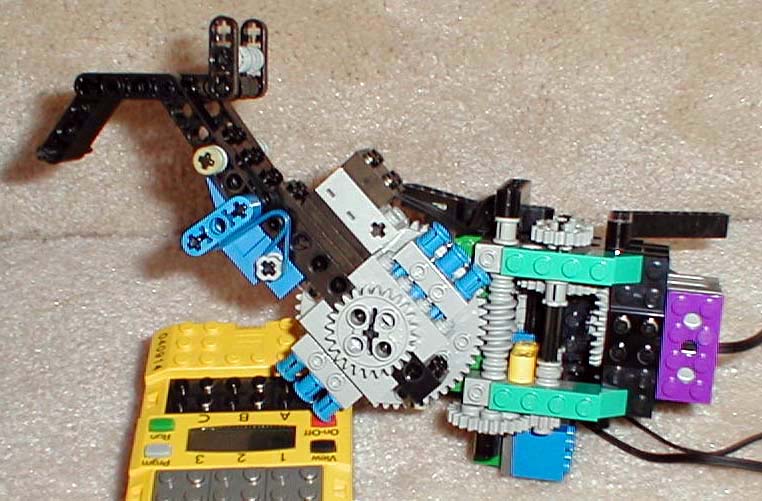
Close-up of the arm/wrist area. Showing the turntable, and the blue rotation sensor. The rotation sensor was used to keep track of each arms position during the climbing operation.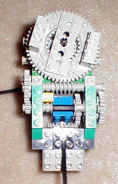
Yet another hand picture.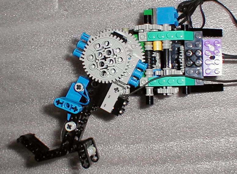
This is the back side of the main torso. This picture was taken before most of the upper body was built. It illustrates 2 mechanisms. The first is the gear train that allows the body to twist or rotate while climbing. The idea is that when an arm reaches up and starts to climb, then robot needs to shift its weight to one side to balance the robot so that it does not twist. This is a trait that we has humans take for granted. Next time you try and swing on a bar, take one hand off and notice how you had to shift your weight to compensate. This also helps to alleviate stress on your hand, wrist and arm. The second component of the torso is the repelling mechanism. This can be seen from the middle to the left (top). The idea here was that Climber would reach the top, toss a rope/hook over the top, engage the mechanism, let both hands go and repel down. Unfortunately, I have yet to test it..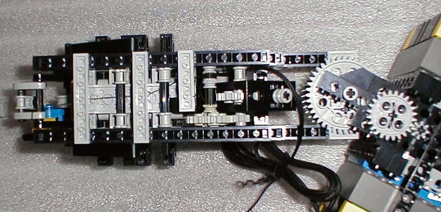
Showing Climber in its main parts all laid out for construction. At the top of the torso, you can see the hook replelling mechanism. The main center shows the motor used to drive the repelling unit.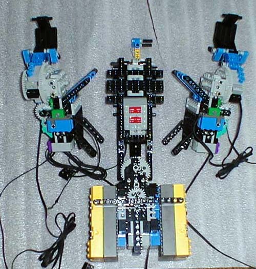
Rate This Post:  (No Ratings Yet)
![]() Loading...
Loading...

Comments: