
UNV
April 2007:
Your first question is probably “what does UNV stand for?”. Well, its nothing special – I simply could not come up with a name for it, so what better way to tag it then simply unnamed vehicle. After receiving a bunch of the new tread links, I wanted to create something grand with them. Scouting the web, I came across these multi-purpose robots (see below) that can be outfitted for police / bomb squad use, or for scientific work. Thought they looked pretty cool, so they were the inspiration. UNV was sitting around for months before I finally got around to taking pictures and a video of it. Read on for details…


UNV can be either an autonomous or remotely controlled robot. The version I have here is controlled remotely by another NXT using Bluetooth. To make it autonomous would simply be extending the software by enabling self-roving features within it. I thought about doing this and having it set-up such that with the BT remote, I could initiate autonomous mode to let it run on its own as well as bring it back to remote control mode – but I simply did not have the time.
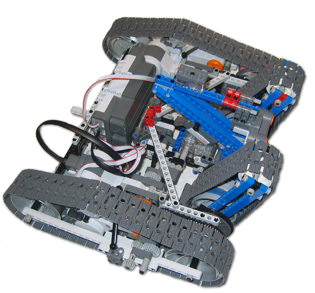
The principle behind the track drive is that like any tank, both drive wheels are controlled independently and can be used to steer the robot on the spot. In addition to this, there are the front center mounted tracks that are linked to each drive track but also can rotate up or down by about 220 degrees. This allows UNV to approach taller objects and use the tracks to “pull” itself up.
I am not that impressed with the performance and strength of UNV – it was just too heavy for its own good. In addition, these new tracks dont offer much in traction. I was hoping that after it was done it would be able to climb objects using the front track tilt mechanism, but again, the weight kills it. (note – video run at 2x speed – so you dont get too bored 🙂
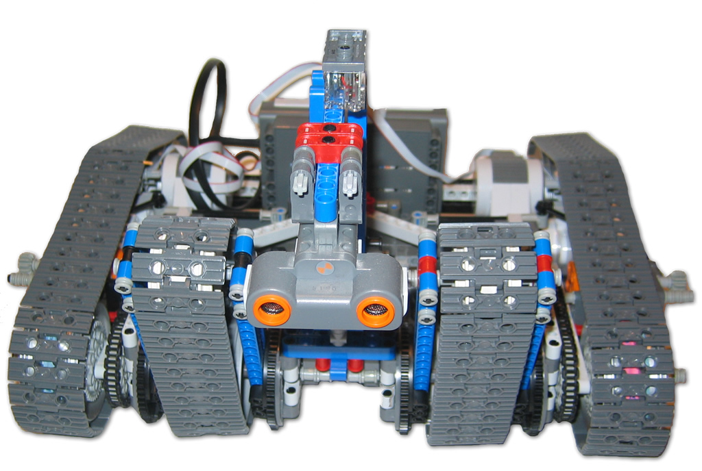
A front view of UNV showing the moveable tracks. The ultrasonic sensor was put on an extendable arm. Although not implemented, the idea was that the robot could extend the US sensor ahead of itself to get a closer “view” of what is ahead without having to navigate right up to an object. The arm was controlled via 4th motor that would have been connected to a Mindsensors MotorMux on a sensor port. You may be wondering what that clear block on top of the arm is – if you noticed it, good eye. Can you tell what it is? Oddly, its a sound block that my brother found on his driveway one day.. He gave it to me and I connected it on UNV for storage, then forgot and only noticed it after I took all these pics.
[ad name=”GoogleAS728x90″]
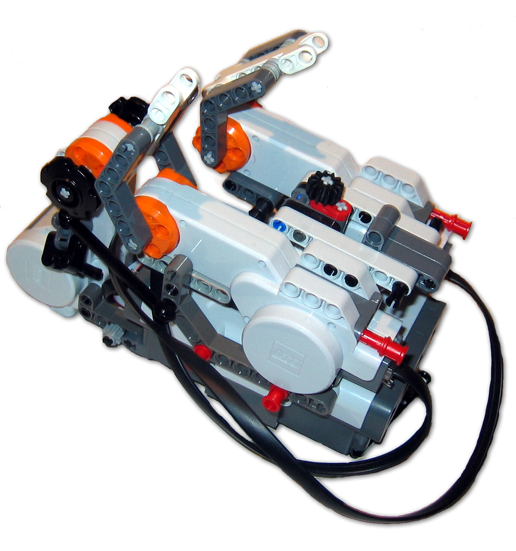
The remote control unit has 3 motors – 2 to drive each wheel and one to control the front track angle. The software was borrowed and modified from Brian Davis’ original Bluetooth remote samples.
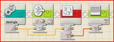
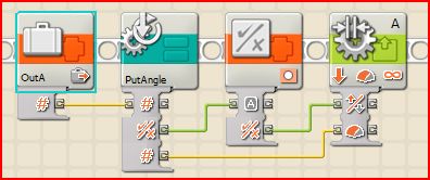
| The concept is pretty straight forward – the remote monitors the rotation value of each motor, it uses a custom MyBlock (GetAngle) and passes the value for each motor via Bluetooth using Mailboxes #1,2,3. The example here also shows the value on the screen. | UNV monitors the mailboxes and when a new message is received, it parses the contents, uses the PutAngle MyBlock to determine both the direction (- is backward, + is forward) and velocity to drive the motors. In the example here, a separate routine parses the mailbox, and when its content changes, it places the value in variable OutA |
 |
 |
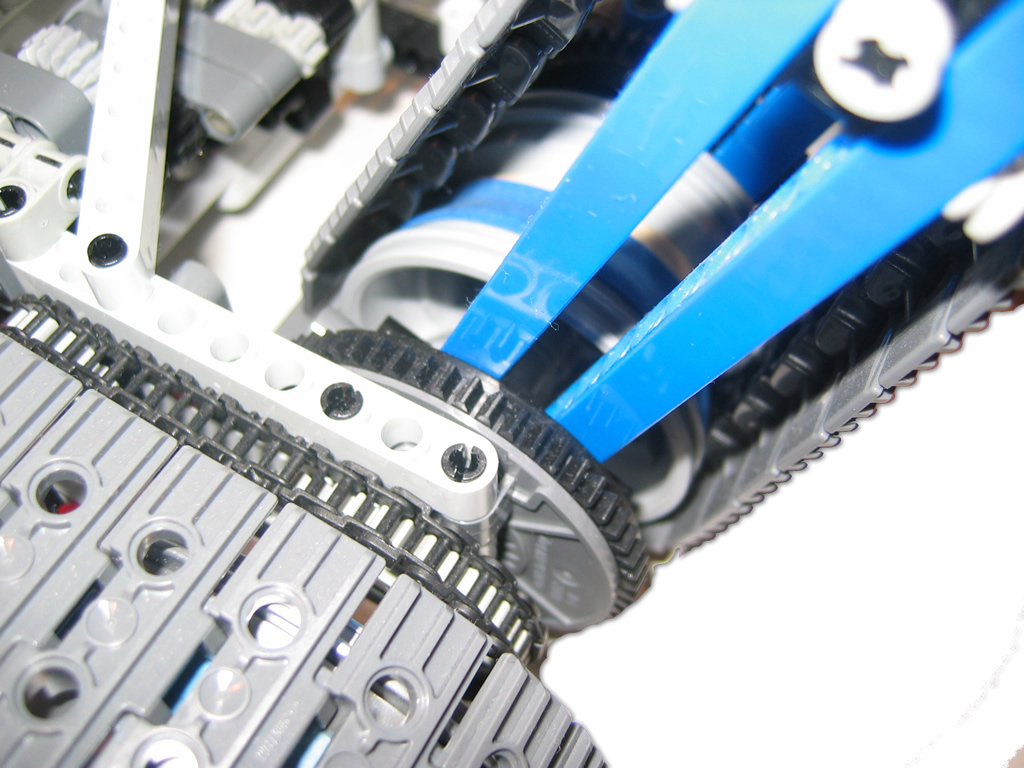
Here is a close-up of the right side drive track showing the turntable used to rotate the front track. You will notice a bit of cheating here with the blue large elastic on the wheel hub. These tracks were not designed to fit these wheel hubs, but with a little help, the elastics provided the friction between the hub and tracks for grip. Now all we need is, oh… something like little rubber nubs to fit in those nice pin holes in the tracks to provide them grip on slippery surfaces. The main drive motors use the smaller chain links to drive each wheel. Unfortunately, this came as a redesign to shift the motors around and they often snapped when the robot was under stress. A direct-drive gearing approach will be used next time.
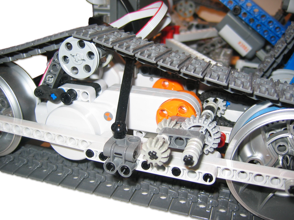
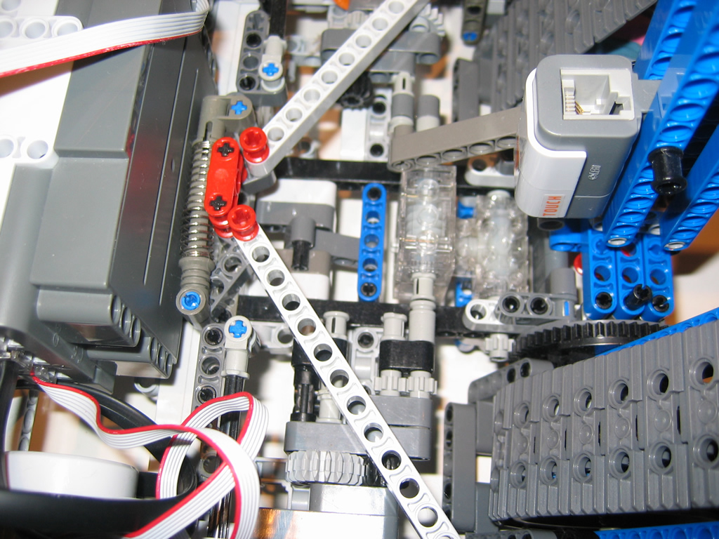
A side-view of the track drive unit. The components were large enough that I was able to mount each drive motor directly within the track drive system. The black pivot beam is used to strengthen the connection between the drive track unit and the main chassis.
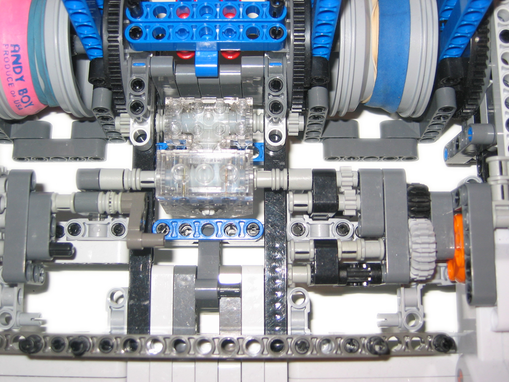
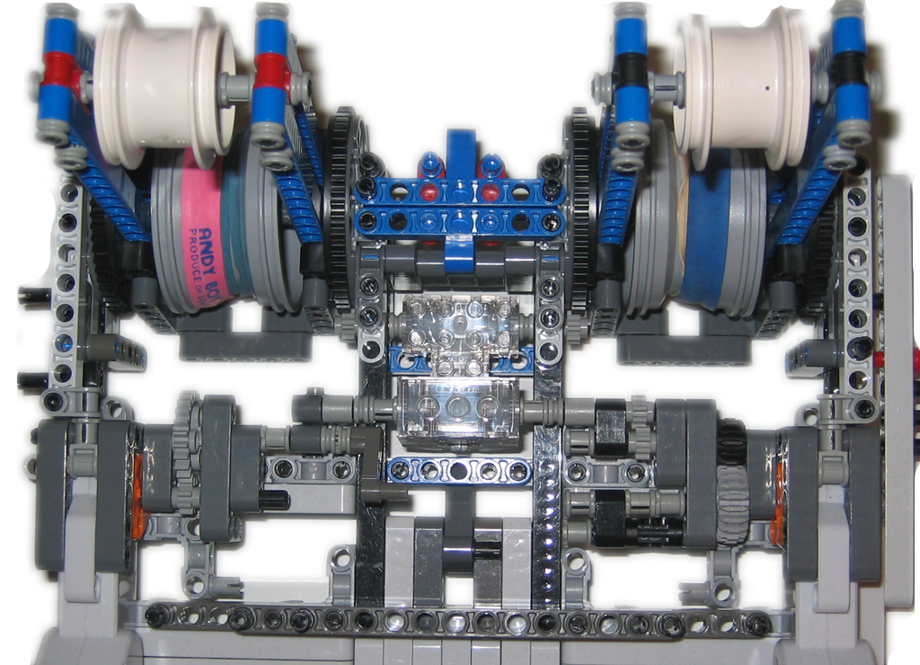
The following pictures were taken to provide some insight to studless building and making strong connections for gearing that is under a great deal of stress. Those 2 clear gear trains in the middle are a worm drive and a “T” drive unit connected to each other. They provide a means to quickly gear down the motor to be able to provide a great deal of torque as well as allow me to connect the drive unit to both track units via an 8 tooth gear connected to the turntables (left and right). That said – the robot was heavy enough that when climbing, sometimes the worm drive (lower clear brick) would skip! The NXT motor to the right drives this unit – from it you can see the amount of gearing that was required to enable the front tracks to lift the robot while climbing. Again, its weight was a factor here. And yes – those elastics are from Andy Boy Broccoli. – Dont forget to eat your broccoli kids!
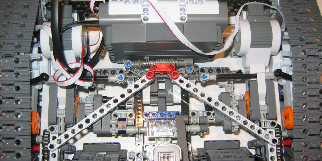
Another view zoomed out. Click to enlarge.
A view of the same from the left side.
Another view from the front looking down.
[ad name=”GoogleAS728x90″]
Rate This Post:  (3 votes, average: 5.00 out of 5)
![]() Loading...
Loading...


Is this from Lego
No, this is my own design.. However, all parts are LEGO parts.