Nissan Juke – Custom LED Tail Lights
I’m a sucker for not conforming to status quo when it comes to my toys.. This includes my new Nissan (2012) Juke. In this mod, I added a set of LED light strips to the tail lights with a twist – I wanted to also monitor and react to braking to enhance the effect. I decided to go with an ATTiny85 using the Arduino core. It only needed 1 input from the 12V brake power and 1 PWM output to control a MOSFET which in turn powered the LED light strip @ 12V. I built one controller per tail light. Check out the video to see it in action:
[ad name=”GoogleAS728x90ImgOnly”]
Some pics of the final result:
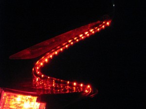
The Build:
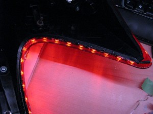
I Ebayed a pair of red LED side-emitting LED light strips from overseas. Side-emitting are necessary due to the design of the Juke tail cluster lense. The mounting of the strip allows these LEDs to shine toward the back of the car rather than out the side.

Mounting the light strip was a bit of a challenge. Not so much in the actual mounting/gluing but rather in the strip quality. When mounting the first strip, it broke half way along the strip and killed power to the downstream LEDs. Poor build quality as it broke along one of the ‘cut lines’. I had to scrape away the clear rubber coating and solder 2 new tiny connectors and re-link the strip back together. All while half the strip was already glued to the tail light. Fun. Guess this is what you get for buying overseas quality…
To mount the strip, I used a glue gun and tacked along every inch or so. The strip itself also has an adhesive backing, but I dont imagine that will last long given that this LED strip will be exposed to the elements (yes, even though this appears to be inside the tail light, there is no rubber seal when mounted back to the vehicle – there is an open gap which will allow the elements in – this is by design, but not sure why Nissan did it this way.
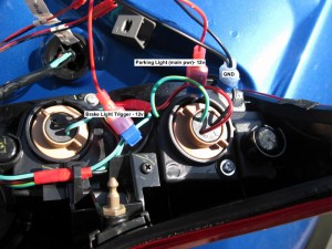
Locating connections for the controller was straight forward. There is 12V main (from the parking light), 12V brake (from the brake light) and ground. The following shows the wires for each of these:
The Electronics:
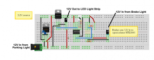
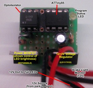
The circuit is pretty straight forward. The heart of the unit is the ATTiny85. 12V power comes in when the parking lights are turned on. This is dropped to 3.3V via a voltage regulator to power the ATTiny85. When the brakes are applied, 12V comes into the optoisolator to allow the ATTiny to detect when the brakes are applied. Since the ATTiny85 can only accept input up to 5V, I needed a way to drop the 12V in from the brakes to something more manageable. I could have used a voltage divider, but I decided the optoisolator approach as it allowed the brake circuit to be completely separate from the parking light circuit. When 12V is applied to the optoisolator, it triggers its output to go low (0V) which is connected to the ATTiny85’s input pin (normally high). This triggers the controller to go from 75% LED power to 100%. The circuit also channels 12V directly to a MOSFET which is controlled by the ATTiny85’s PWM output pin. On normal startup, it PWM’s the LEDs up to 75%. When brakes are applied, it goes temporarily to 100% then back.
The controller. In order to make the circuit weather resistant, I dipped it in PlastiDip. I still have the ATTiny85 and optoisolator chips exposed as I may want to change the code before committing.
Source Code:
/*
Control LED light strip via 12V power provided by parking lights (rear red). Additionally,
the actuation of the brake lights will also illuminate the LED strip at a brighter level to allow it to
enhance the effectiveness and visibility of the rear brake lights
Design:
12V main to power the arduino (ATTiny85) (via 3.3v regulated circuit). 12V main also directly powers the LED light strip.
However, the Arduino will be used to control a MOSFET via PWM to act as a light level controller. On start
the LEDs will automatically 'ramp up' to specific light intensity, but not 100% power. When the brake lights
are applied, the Arduino will detect this on an input pin and turn the LEDs on to full brightness, and then
back off once the brakes are no longer applied.
*/

byte ledMaxVal = 255; //Full LED brightness level - to be applied when brakes are on.
byte ledNormVal = 100; //normal LED light level.
boolean ledState = 0; //The current state of the LEDs. 0=off 1=on
boolean ledAtMax = 0;
//boolean brakeState = 0; //The current state of the brake detected on brakePin. 0=off 1=on
//int brakeV = 0; //Mapped value converted read from brakePin mapped from 0-1023 to 0-5V. Note Brake pin has a pull down resistor of 10K to have it read 0 by default.
int flashCounter = 0;
int brakeThresh = 500; //brake threshold. Pin is high. When brakes applied, pin drops to near 0V. value in mV

//Configurable values
const int LEDPin = 1; //output pin to control MOSFET switching to power the LED strip from 12V.
const int brakePin = 3; //pin that will detect when brake lights are on.
const int LEDstatPin = 0;

void flash() {
  digitalWrite(LEDstatPin, HIGH);
  delay(20);
  digitalWrite(LEDstatPin, LOW);
}

void rampLEDDownNoff(byte lval, int dly)
{
  while (lval > 0)
  {
    analogWrite(LEDPin, lval);
    lval--;
    delay(dly);
  }
  //make sure they are all off
  digitalWrite(LEDPin, LOW);
  ledState = 0;
}

void rampLEDupOn(byte lval, byte ledNormVal, int dly)
{
  while (lval < ledNormVal)
  {
    //give the LED a pulsing look
    //if (lval > 20) {
    //analogWrite(LEDPin,20);
    //delay(5);
    //}
    //comment the above to get rid of the LED pulsing.

    analogWrite(LEDPin, lval);
    //analogWrite(LEDstatPin, lval); //flash the status LED to show that the LEDs are ramping up.
    flash();
    lval++;

    //often, the brake lights will be applied on vehicle start. If this is the case, then just go to full power on the LEDs and
    //stop the remp-up procedure
    if (analogRead(brakePin) < brakeThresh) { // bail out on sensor detect
      analogWrite(LEDPin, ledMaxVal);
      ledState = 1;
      break;
    }

    delay(dly);
  }
  ledState = 1;
}

void setup()
{
  //Serial.begin(9600);
  pinMode(LEDPin, OUTPUT);
  pinMode(LEDstatPin, OUTPUT);
  pinMode(brakePin, INPUT);
}

void loop()
{

  if (ledState == 0) //LEDs are not on, turn them on.
  {

    rampLEDupOn(0, ledNormVal, 20);
    analogWrite(LEDstatPin, 100);
  }

  else if (analogRead(brakePin) < brakeThresh) //ledState would be 1
    //Optoisolator keeps brakePin Hi at 5V. When 12V applied (brake light), pulls brakePin low. Hi=1023. Just picked an arbitrary # of 500
    //if (analogRead(brakePin) < brakeThresh && ledState == 1)
  {
    //brakeState = 1;
    analogWrite(LEDPin, ledMaxVal);
    ledAtMax = 1;
  }
  else if (ledAtMax)
  {
    //brakeState = 0;
    analogWrite(LEDPin, ledNormVal);
    ledAtMax = 0;
  }

  //Serial.print("brkState=");
  // Serial.print(brakeState, DEC);
  //Serial.print(" brkPinV=");
  // Serial.print(brakeV, DEC);
  //Serial.print(" brkPinRaw=");
  //Serial.print(analogRead(brakePin), DEC);
  // Serial.print(" flsCnt=");
  //Serial.print(flashCounter, DEC);

  //Serial.println();

  flashCounter++;

  if (flashCounter == 20)
  {
    flash();
    flashCounter = 0;
  }

  delay(20); //give the processor some breathing time.
  //brakeV = 0;

}
Lessons learned: I should have learned this one a long time ago - don't rush. I figure I will have to re-mount the strips again as I don't like the fit. The Juke tail innards is too tight in some spots to allow the light strip to fit nicely and consistently inside and pointing to the rear. I plan to take a dremmel in there next time to open it up a bit. I also want to figure out why there is a lag in timing when the brake light is applied and when the LED goes to 100%. When being tested, it was immediate.
After watching the videos a few times, I noticed a lag in the time from when the LED strip comes on and when the actual brake light fully illuminates. I think this is due to the time it takes for the incandescent bulb to reach its max brightness. However, the LEDs are able to reach instantaneously. I've re-programmed the ATTiny to delay the LED 75% to 100% trigger timing by a few hundred milliseconds to make up for the brake light bulb and come on at the same time.
Future ideas - I am waiting to see if the digitally addressable RGB LEDs can be made thinner/less wide to fit the Juke tails. I have some ideas about the power on phase (eg have the LEDs ramp up or down one LED at a time, allow interaction with the brakes (red) as well as the signals (amber)...


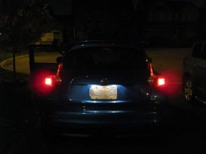



little led bulbs make car back lights better.great work
Cool. Been thinking of doing something like this for my 2010 honda.
Delaying the 100% on the leds is foolish, the sooner that your brake lights come on, the sooner someone behind you can hit theirs, the speed of LED responsiveness is one of the big advantages of them.
that partial second you’re delaying the leds means that someone behind you is that much closer to rear ending you.
Your logic would be correct if these LEDs were meant to be the main means to indicate braking. However, what you cannot see from the pics/video in this blog as that these LEDs are not that bright. Their original intent was to be accent lighting to compliment the parking lights that come on. I enhanced the functionality to allow them to work along with the brakes for the effect. BTW – I have already decided that I won’t add the lag for the very logic you described.