
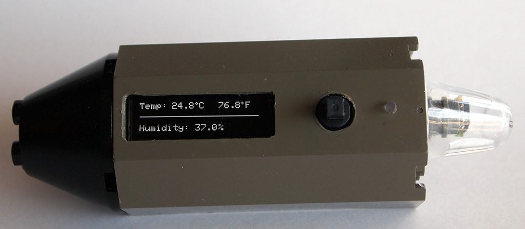
Arduino Temperature / Humidity Sensor
The projects I do tend to fall in one of two buckets – either proof-of-concept (so I can learn new stuff) or items that have some sort of functional use.  The need for this project came about when my wife was prodding me about the humidity in the house and whether our humidifier was doing it’s job correctly. Most people would just go out and buy a temp / humidity sensor and be done with it. However, if you have a look around here, you will see that I don’t fit that mold. Instead, I decided to build an accurate temp / humidity sensor with a Sensiron SHT11 to read the values, a RBBB Arduino kit to process everything and an Adafruit 128×32 OLED to display the results – all wrapped up in… LEGO! Read on for more…
Admittedly, I would not normally spend the money required to outright build this gizmo (approx $95 incl shipping for all parts). Instead, I was able to acquire the parts for a fraction of this price. As a result, the purpose of this build is twofold. 1) Create a sensor that can be used in my house on an ongoing basis; 2) Review the parts to provide insight for those considering using them for similar or other projects.
Parts:
- Adafruit Monochrome 128×32 OLED Display – ($17.50)
- Newark Sensiron SHT11 Humidity / Temperature Sensor ($29.xx)
- Modern Device RBBB Arduino Kit (3.3v) ($13.00)
- Adafruit Through Hole 5-Way Navigation Switch ($2.95)
- Insulated Silver-Plated Copper 30Ga Wire (~1.00)
- The rest of the parts (caps, resistors, LED) I had as spares.
There were a few goals that I wanted to achieve with this project. Make it small and compact, easy to use, and conserve as little power as possible. Getting it into a small package was aided by the RBBB. I could have gone a step further by just making a standalone Atmega, but the LEGO shell was my starting place and everything fit fine within the space it had. For power conservation, I used the sleep abilities of the chip and tied it to Interrupt2 tied to the toggle switch. Pushing the switch ‘in’ would trigger the interrupt and wake the unit. I also have power for the OLED and the SHT11 sensor shut down just before it goes to sleep, and back on immediately after it wakes. To do this, I used 2 digital pins set to HIGH / LOW as needed. I am running the unit off 2x 3V 2032 cells in series, which are put through a 3.3v regulator to power the board and components. When running with all components powered it pulls 12mA. In sleep mode it pulls 0.6mA. I’d like to get it lower, but think that my use of the regulator is partially killing it due to the voltage drop out.
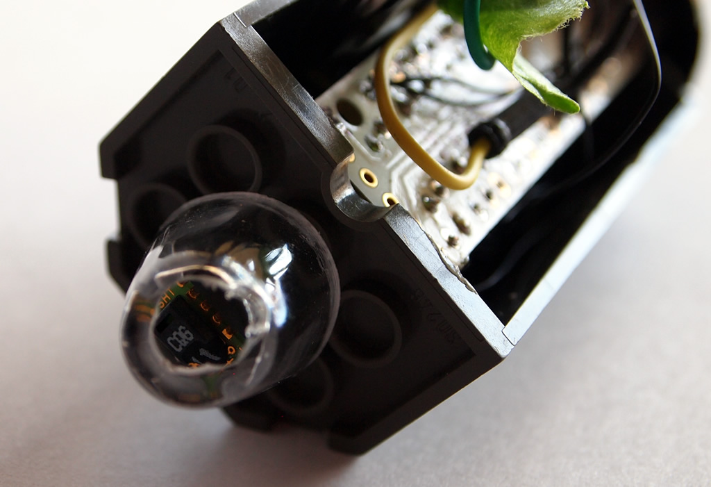
 The key to the accurate humidity / temp readings is the Sensiron SHT11 sensor. It’s tiny – really tiny. There are 4 connections: 3.3V- 5V, GND, Data, CLK. In order to protect the sensor, it has been mounted to the side of the unit inside a clear plastic housing. The housing has a hole in the side to allow air to flow freely, but limits the any water that might find its way in there (because you never know when it might rain inside the house 😉
[ad name=”GoogleAS728x90ImgOnly”]
Since everything is so small, I used very fine 30 gauge silver plated copper wire for this. It worked quite well for what I needed to do here.
Before migrating all the components into the project, I set everything up on a breadboard and used the Uno to test the sketches. Interestingly, I found getting the 5-way switch working the most challenging. It has a common anode I am using as both an Interrupt link (Pin2) as well as toggle switch for scrolling the OLED.
[ad name=”GoogleAS728x90ImgOnly”]

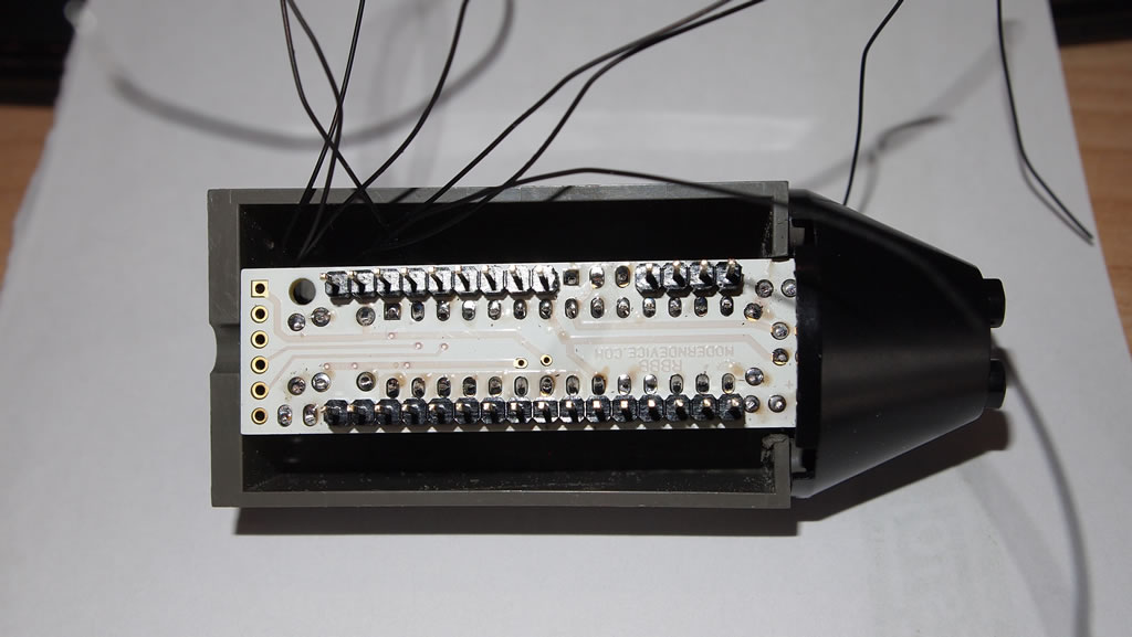
Below showing the completed RBBB kit. Initially, this came with an earlier Bootloader, but I updated to the Uno one with ease.

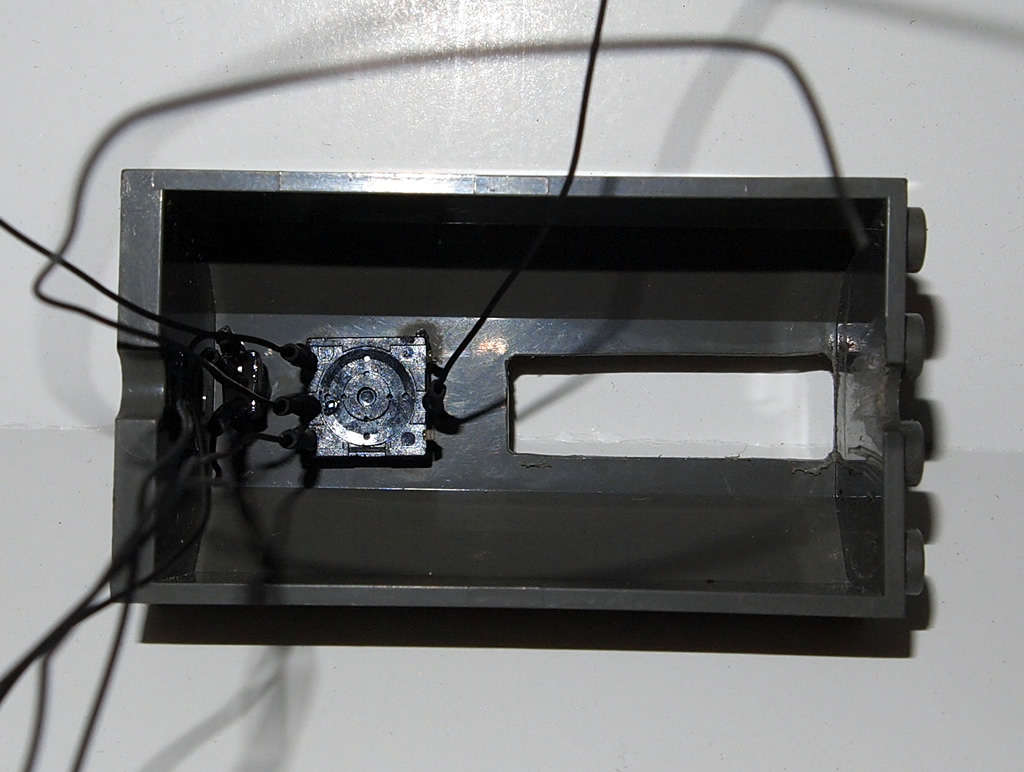
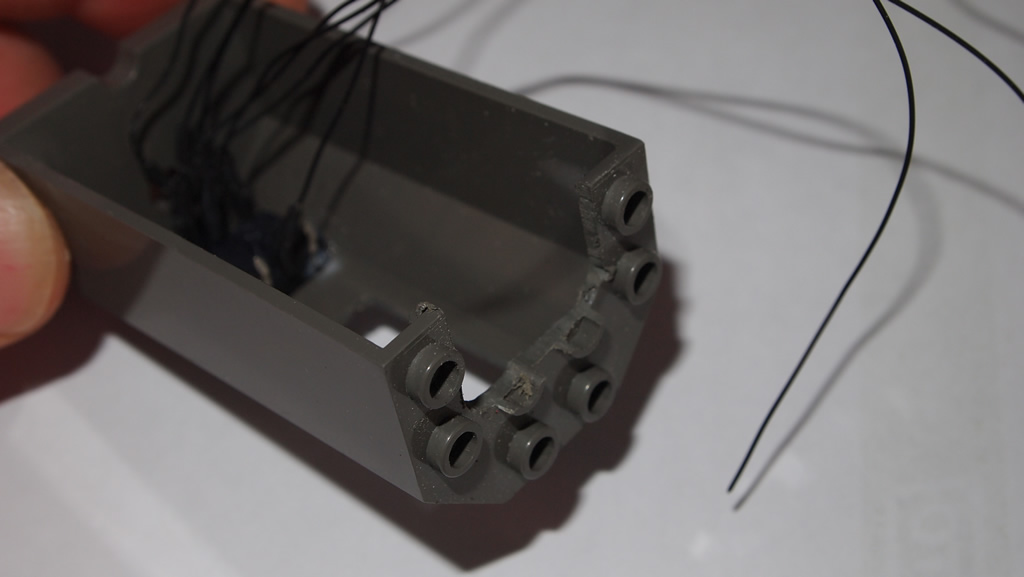
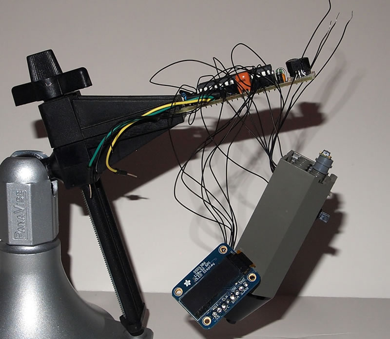
The next step was to start fitting the components into the case. The first parts to go in were the switch and red/green status LED. The LED was a pull from an old portable DVD player. After that was done, one side was cut to make room for the length of the RBBB kit. Being a die-hard LEGO fan and spending most of my life building, I was always against bastardizing LEGO for things like this – until I discovered Arduino / micro-controllers. Sorry AFOL’s. 🙂 The 3rd pic shows the bits all soldered together using that nice 30Ga wire. The 4th shows a test fit with the RBBB inserted. I made the mistake of completing the RBBB kit as per instructions only to realize that I did not want the rows of breadboard pins as would not need them.. So, out came the solder sucker and I removed them (hence the burn marks you see in other pics). In the last picture, you can see a side view showing the SHT11 sensor.. Did I mention this thing is tiny!?

The Verdict:
Adafruit 128×32 OLED: If you are looking for a crisp display with a small footprint, then this is the unit for you. Don’t expect to be able to read this thing from afar. However, up close, the display is clear, and crisp. Because it does not have a backlight, and each pixel is self- illuminated, it has low power consumption and is easy to read. Out of the box, the display is slow to render for anything where rapid updates are necessary. However, the driver can easily be modified to use the Arduino SPI hardware to speed up its response. For this purpose, its not really necessary as I am not drawing rapid graphics or animating. If you are doing that, then you want to do this easy mod. Just remember that you must then also use the dedicated hardware SPI pins.
Sensiron SHT11: Did I mention the sensor is small? Ok, I know I did – so it’s small. This is great for integrating it into small projects like this. Sensiron claims the unit has a high degree of accuracy (+/- 0.4’C and +/-3% RH). When pitching the results against other temperature gauges in our house, I had different readings on all of them. When I tested the readings against a classic mercury unit, it was off by about 1 degree. It also responded well to rapid temperature changes at about a 1-2 hz rate. Not super fast, but good enough for measuring changes in room temperature. I did some tests where I set the update frequency to less than 500 Ms and it still took about 1+ seconds to return a result – so it seems that the sensor requires this time to produce and return an accurate reading.
[ad name=”GoogleAS728x90ImgOnly”]
Modern Device RBBB Kit: If you are looking for a small Arduino footprint, then this is a nice unit. It is not the smallest out there, but good enough for most small projects. For the price of about $13 plus shipping you can get a full setup in either 3.3v or 5v, the board, parts and an Atmega 328P with bootloader. The only caveat is that it comes with the Diecimila Bootloader, but you can change it to whatever you like easily. Yes, I could have put together a standalone kit with a little more soldering, but considering time and cost, it is not really worth it.
The Code: (download it)
#include //SSD #include //for OLED #include#include #include //HumidityTemp Sensor SHT11 //OLED PINS #define OLED_RESET 7 // RST on OLED #define OLED_DC 8 // S/C on OLED #define OLED_CS 6 // CS on OLED - SPI slave-select #define OLED_MOSI 11 // DATA on OLED - hardware SPI MOSI #define OLED_CLK 13 // CLK on OLED - hardware SPI clock //SHT11 Tmp/Humidity Sensor // Specify data and clock connections and instantiate SHT1x object #define dataPin 9 //#define clockPin 11 #define clockPin 10 SHT1x sht1x(dataPin, clockPin); float temp_c; float temp_f; float humidity; //#define SHTPwrPin 4 -not used. When using this, current draw went from 0.6mA when off to 37mA when off!!!! put back //to 5V pin and back to 0.6mA when off - much better! #define OLEDPwrPin 3 int redLED = A2; int grnLED = A3; int LEDcounter = 0; int SHTReadCounter = 0; int centerToggle = 2; int upToggle = 12; int dnToggle = 5; //switch debouncing long debounceDelay = 20; // the debounce time; increase if the output flickers - long lastDebounceTime = 0; // the last time the output pin was toggled //for up toggle int upButtonState; // the current reading from the input pin int upLastButtonState = LOW; // the previous reading from the input pin //for down toggle int dnButtonState; // the current reading from the input pin int dnLastButtonState = LOW; // the previous reading from the input pin //end switch debouncing volatile int toggle = 1; char cVal[32]; int displayState = 1; //up and down toggles will change the display to different states long shutoffStartMillis = 0; //Store the value to start the shutoff timer from in Milliseconds. //********************************** //Change this to determine how long the device stays on - in MS long shutOffDelayMS = 180000; //In Milliseconds - Determines how long to keep LED system on (after shutoff timer clicked) in Milliseconds 10000 (10sec), 60000 (1min) 600000 (10min) //********************************** boolean debug = false; //turn debugging on or off here //OLED SSD1306 oled(OLED_MOSI, OLED_CLK, OLED_DC, OLED_RESET, OLED_CS); void (*restart)(void) = 0; /*************************************************** * Name: pin2Interrupt * ***************************************************/ void pin2Interrupt(void) { /* This will bring us back from sleep. */ /* We detach the interrupt to stop it from * continuously firing while the interrupt pin * is low. */ //appears that the interrup is not working correctly and re-triggering things. Try a restart instead restart(); // - removed while testing restart() function. Put these back if restart removed //toggle = 1; //delay(100); detachInterrupt(0); } /*************************************************** * Description: Enters the arduino into sleep mode. ***************************************************/ void enterSleep(void) { /* Setup pin2 as an interrupt and attach handler. */ //attachInterrupt(interrupt, function, mode) //attachInterrupt(0, pin2Interrupt, LOW); attachInterrupt(0, pin2Interrupt, FALLING); delay(100); //Serial.println("Going to sleep...."); set_sleep_mode(SLEEP_MODE_PWR_DOWN); sleep_enable(); sleep_mode(); /* The program will continue from here. */ /* First thing to do is disable sleep. */ sleep_disable(); } void setup() { Serial.begin(38400); pinMode(A5, OUTPUT); //testing blink /* Setup the pin direction. */ pinMode(centerToggle, INPUT); //pinMode(SHTPwrPin, OUTPUT); pinMode(OLEDPwrPin, OUTPUT); pinMode(redLED, OUTPUT); pinMode(grnLED, OUTPUT); digitalWrite(grnLED, HIGH); //turn off the green LED - common annode - so they have to be high digitalWrite(redLED, HIGH); //turn off the gred LED - common annode - so they have to be high digitalWrite(upToggle, LOW); digitalWrite(dnToggle, LOW); //digitalWrite(SHTPwrPin, LOW); digitalWrite(OLEDPwrPin, LOW); //********* OLED SETUP STUFF ******************************************************************/ SPI.begin (); //for OLED // OLED: By default, we'll generate the high voltage from the 3.3v line internally! (neat!) oled.ssd1306_init(SSD1306_SWITCHCAPVCC); //********* OLED SETUP STUFF ******************************************************************/ //oled.clear(); //oled.display(); // displayState = 1; if (debug) { Serial.println("Initialisation complete."); Serial.println("Entering sleep"); } //delay(200); //enterSleep(); oled.clear(); } void doHumTmp(void) { // Read values from the sensor if (SHTReadCounter == 20) //this is based on the delay at the bottom. if delay changes, this value should as well { temp_c = sht1x.readTemperatureC(); temp_f = sht1x.readTemperatureF(); humidity = sht1x.readHumidity(); SHTReadCounter = 0; if (debug) { // Print the values to the serial port Serial.print("Temperature: "); Serial.print(temp_c, DEC); Serial.print("C / "); Serial.print(temp_f, DEC); Serial.print("F. Humidity: "); Serial.print(humidity); Serial.println("%"); } } oled.clear(); if (temp_c < 0 || temp_f < 0 || humidity < 0) { //calibrating // oled.drawstring([character position from left - by pixel], [line number 0,1,2,3], "[text]"); blinkLED(redLED); oled.drawline(0, 9, 128, 9, WHITE); oled.drawstring(0, 2, "Calibrating..."); oled.drawline(0, 30, 128, 30, WHITE); } else if(displayState == 1) //good readings show - 2 display states { blinkLED(grnLED); //Temp in C and F oled.drawstring(0, 0, "Temp: "); ftoa(cVal, temp_c, 1); oled.drawstring(35, 0, cVal); //oled.drawchar(65, 0, 9); //draw degree symbol //oled.drawcircle([x position px], [y pos line], [diameter units??], WHITE); oled.drawcircle(61, 1, 1.5, WHITE); oled.drawstring(64, 0, "C"); //degrees F ftoa(cVal, temp_f, 1); oled.drawstring(85, 0, cVal); //oled.drawchar(115, 0, 9); oled.drawcircle(110, 1, 1.5, WHITE); oled.drawstring(114, 0, "F"); //draw split line oled.drawline(0, 15, 128, 15, WHITE); /* int upstate = digitalRead(upToggle); itoa(upstate, cVal, 0); oled.drawstring(0, 2, "up:"); oled.drawstring(10, 2, cVal); int dnstate = digitalRead(dnToggle); itoa(dnstate, cVal, 0); oled.drawstring(45, 2, "dn:"); oled.drawstring(50, 2, cVal); */ ftoa(cVal, humidity, 1); oled.drawstring(0, 3, "Humidity:"); oled.drawstring(60, 3, cVal); oled.drawstring(85, 3, "%"); } else if (displayState == 2) //display state would be 2 here { blinkLED(grnLED); oled.drawstring(0, 0, "Sensor: Sensiron SHT11 Temp & Humidity"); oled.drawstring(0, 2, "OLED:Adaft SSD1306 128x32"); } else if (displayState == 3) { blinkLED(grnLED); oled.drawstring(0, 0, "Board: Modern Device RBBB Kit"); oled.drawstring(0, 2, "Chip: Atmega 328P w/UNO Bootloader"); } else if (displayState == 4) { blinkLED(grnLED); oled.drawstring(0, 0, "Sketch:"); oled.drawstring(0, 1, "HumidityTempSensor1_4"); } //Display all the results oled.display(); delay(100); SHTReadCounter++ ; } /*************************************************** * Name: loop * Description: Main application loop. * Operation Our code will operate as follows: 1.Set up the serial port and set pin 2 (INT0) as an input; 2. Run the loop function which will: 3. Stay awake for 3 seconds; 4. Once the 3 seconds have elapsed, SLEEP_MODE_PWR_DOWN will be entered; 5. All code execution stops; 6. The user then pushes the switch and pin 2 (INT0) will become low; 7. The INT0 interrupt will fire and bring the Arduino out of sleep mode; 8. Code execution continues where it had previously stopped. Circuit: http://donalmorrissey.blogspot.com/2010/04/arduino-external-interrupts.html ***************************************************/ //int seconds=0; void loop() { if (debug) { // Serial.println("Still awake...."); } //Will put the unit to sleep after a pre-defined amount of time if (shutoffStartMillis != 0 && millis() - shutoffStartMillis > shutOffDelayMS) //if shutoff time has elapsed, turn the LEDs off 1000ms = 1 second { //delay(100); shutoffStartMillis = 0; //power down the SHT11 Sensor and other ports digitalWrite(upToggle, LOW); digitalWrite(dnToggle, LOW); //digitalWrite(SHTPwrPin, LOW); //Power down the OLED oled.clear(); oled.display(); //digitalWrite(OLED_RESET, LOW); digitalWrite(OLEDPwrPin, LOW); //go to sleep if (debug) { Serial.println("Entering sleep"); } delay(200); //seconds = 0; enterSleep(); } //watch the up and down toggle //int upToggleReading = digitalRead(upToggle); //int dnToggleReading = digitalRead(dnToggle); //will be able to read each other toggle pin as LOW when it is pressed. if (debug) { // Serial.print("UpToggle: "); Serial.print(digitalRead(upToggle)); // Read the pin and display the value // Serial.print(" DnToggle: "); Serial.println(digitalRead(dnToggle)); // Read the pin and display the value // Serial.print(" DisplayState: "); Serial.println(displayState); // Read the pin and display the value } if (digitalRead(upToggle) == 0) { //displayState++; //if (displayState > 2) {displayState = 1;} //simple method to only go to 2 states displayState = 1; delay(100); } if (digitalRead(dnToggle) == 0) { //if (displayState < 1) {displayState = 2;} //simple method to only go to 2 states if (displayState < 4) { displayState++; } //dont let it go past a max value delay(100); } /* Serial.print("ButtonState: "); Serial.print(upButtonState); Serial.print(" LastButtonState: "); Serial.print(upLastButtonState); Serial.print(" DisplayState: "); Serial.println(displayState); Serial.print("ButtonState: "); Serial.print(dnButtonState); Serial.print(" LastButtonState: "); Serial.print(dnLastButtonState); Serial.print(" DisplayState: "); Serial.println(displayState); */ // save the reading. Next time through the loop, // it'll be the lastButtonState: //upLastButtonState = upToggleReading; //dnLastButtonState = dnToggleReading; if (toggle == 1) { shutoffStartMillis = millis(); //get a start value to start the countdown from. displayState = 1; //ensure the display defaults to the main screen //digitalWrite(SHTPwrPin, HIGH); digitalWrite(OLEDPwrPin, HIGH); delay(1000); //********* OLED SETUP STUFF ******************************************************************/ //have to do this again with each power on state or the OLED does not come on. SPI.begin (); //for OLED // OLED: By default, we'll generate the high voltage from the 3.3v line internally! (neat!) oled.ssd1306_init(SSD1306_SWITCHCAPVCC); //********* OLED SETUP STUFF ******************************************************************/ delay(500); //oled.clear(); //oled.display(); doHumTmp(); //provide power to the toggle switch up and down. digitalWrite(upToggle, HIGH); digitalWrite(dnToggle, HIGH); delay(500); //give it some time to calibrate etc toggle = 0; } else { //show the temp and humidity values doHumTmp(); } LEDcounter++; } //~~~~~~~~~~~~~~~~~~~~~~~~~~~~~~~~~~~~~~~~~~~~~~~~~~~~~~~~~~~~~~~~~~~~~~~~~~~~~~~~~~~~~~~~~~~~~~~~~~~~~~~~~~~~~~~~~~~~~~~~~~~~~~~~~~~~ char *ftoa(char *a, double f, int precision) { long p[] = {0, 10, 100, 1000, 10000, 100000, 1000000, 10000000, 100000000}; char *ret = a; long heiltal = (long)f; itoa(heiltal, a, 10); while (*a != '\0') a++; *a++ = '.'; long desimal = abs((long)((f - heiltal) * p[precision])); itoa(desimal, a, 10); return ret; } //~~~~~~~~~~~~~~~~~~~~~~~~~~~~~~~~~~~~~~~~~~~~~~~~~~~~~~~~~~~~~~~~~~ static void print_str(const char *str, int len) { int slen = strlen(str); for (int i = 0; i < len; ++i) Serial.print(i } //~~~~~~~~~~~~~~~~~~~~~~~~~~~~~~~~~~~~~~~~~~~~~~~~~~~~~~~~~~~~~~~~~~ static void print_int(unsigned long val, unsigned long invalid, int len) { char sz[32]; if (val == invalid) strcpy(sz, "*******"); else sprintf(sz, "%ld", val); sz[len] = 0; for (int i = strlen(sz); i < len; ++i) sz[i] = ' '; if (len > 0) sz[len - 1] = ' '; Serial.print(sz); } void blinkLED(int led) { if (LEDcounter == 10) //we do not want the LED blinking with every cycle as it is seizure enducing! { if (led == redLED) { digitalWrite(redLED, LOW); delay(50); digitalWrite(redLED, HIGH); } else { digitalWrite(grnLED, LOW); delay(50); digitalWrite(grnLED, HIGH); } LEDcounter = 0; } }


Hi There, nice project. I have recently completed the code for Arduino using a similar (though cheaper, less accurate and bigger) sensor the DHT-11.
Your code is a bit mangled with HTML formatting now included, this makes it a little hard to read and understand it. Perhaps you could link to the files for download? That way interested people could examine it for themselves.
I personally use Github these days to keep my code. You can see my Temperature and Humidity sensor sketch there. https://github.com/Justblair/Arduino-Based-Humidex-Meter
Mine has a different purpose in mind to yours, it measures how comfortable a room is and logs this to SD.
Regards
Blair
Dear developer of this great needed tool,
I am really interesting to it and may be could yo help me for the need I will explain here.
I am interesting to also have a Arduino temperature / humidity evaluator but in a fixed mode.
As it must have three specifications I explain it to you :
1) I need to have a Arduino that is able to read temperature and humidity (you just made it 😉 )
2) As I need to be able to extract both ;
a) hot air from my attic and
b) hot and humid air from my bath room
this Arduino with temperature and humidity detection (explained on the point 1) ) must be able to activate a big computer fan
3) it could be appreciate if it could be connected to a computer (or a ethernet router) that can then read the temperature and humidity and be able to specify (through a webpage) the limitatin of temperature and / or humidity that must start the air extraction
4) “cherry on the cake” the Arduino could be also powered even by pppoe
As I still never start to use Arduino do you thing this could be realized ?
Sincerely thanks and have a nice day,
Miguipda 😉
Hi, it seems that what you described is possible with the Arduino and some additional hardware. You indicated pppoe (Point to Point Protocol over Ethernet). I think you meant to say PoE (Power over Ethernet). You can power an arduino and most components using a PoE-enabled Ethernet shield. However, you would have to look at the total current demand of your project (specifically your fan) and see what can be supported by the switch you would be using for your network (since it will be providing the PoE power as well). Also, you would have to determine if a computer fan would provide sufficient draw to move the air out of your attic. Most bathroom fans are 60+ CFM, and I don’t think computer fans are this powerful (lower voltage and speed). Good luck with your project!
I’m considering putting an arduino in the master bath to monitor humidity levels and throw a relay switch that I’ll wire the main bathroom fan to. Then, when humidity levels are back down to a more “normal” level reset the relay to turn the fan off so we can leave the fan running after we’ve left the room, but not have to come back to turn it off.
Nice writeup! I’m a software guy at heart who’s just recently started playing with Arduino and hardware and your writeups are very well done. Keep ’em up!
Hi, congratulations for your work!
I have the SHT11 humidity and temperature sensor and the arduino uno board so i tried to compile your code.
However, the compiler does not find the libraries that you mention.. Where can I find these libraries?? As far as the avr/sleep and the avr/power, would I use the library avr? Also, I am not going to use the OLED display.. Do you have a simplier code to suggest? I just want to see the results of humidity and temperature on the serial monitor of arduino. My final target is to switch on a dehumidifier via a relay board but i can’t go on unless I take the right results from the sensor. Your help would be very important to me, because I have to finish my final year project. Thank you in advance.