Pulito – Beacon (Version 1) Internals
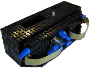
OLD Version Details: (see new version here): The following is a picture of the charging beacon. Although it looks quite plain from the outside, it is what is inside that resulted in this being a 5 month build (well that and things like kids! 🙂 ) From the top there is a cutout for the LCD. The purpose of the LCD is to display the change from 1200 to 600 Hz. The gray axle on top is used to swap between frequencies. These frequencies are tuned to work with the HT IR Seeker V2 sensor on Pulito. Together they allow Pulito to detect the beacon from across the room in many varying conditions (incl bright sunlinght). As many of you know, IR is everywhere, so the 1200Hz is used to allow robots to tune into a specific frequency while ignoring other sources of IR. At the front, the 2 charge bars can be seen. These allow Pulito to dock to the unit and begin charging. At the center in the front, the blue cylinder contains 3 IR LEDs. These LEDs are connected internally to a Basic Stamp II Sx which drives a 1200/600 Hz pulse through a separate 555 timer that generates a 38Khz carrier wave. Together the 1200Hz and 38KHz carrier allow the HT IR Seeker V2 to find the beacon.
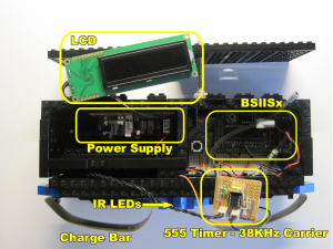
An inside view of the beacon from the top. The LCD (top left) has been removed to show the power supply (left). The power supply was custom built to provide a number of both 5 and 9V power sources (driven by LM7805’s and 7809’s and caps) to provide smooth power for the various components. The unit works as follows:
The BSIISx generates the 1200Hz pulse (powered by 5V)
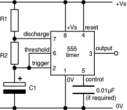
The 555 timer is powered by 5V as well and is triggered by an output pin from the BSIISx. The pin will pulse at 1200Hz and each pulse that is HIGH will trigger the 555 timer HIGH which is outputting its signal at 38KHz. The output of the 555 timer triggers a transistor that switches a dedicated run from a 9V power supply to switch the 3 IR LED’s on/off at high frequency. I wanted the LED’s to have as much power as possible – hence the dedicated 9V supply for them. This way I can add more LED’s if necessary at a later time.
The switch in the center is connected to another pin on the BSIISx and is being read as an input. When it is clicked and held, as the code loops it detects this and switches from 1200 to 600 Hz. And vice-versa.
To the left (can’t be seen here) an external wall wart runs 12 Volts into the system (more like 14V). This is all regulated using the power supply. Additionally, a dedicated (fused) like runs directly to the 2 charge bars (brass things at the bottom left and right) which bring 14V to the Pulito charging system. The fuse is necessary in case there is ever a short across the charge cars (read as my 3 yr old son likes to explore). Of course, its only 14V and pretty much harmless.
[ad name=”GoogleAS728x90ImgOnly”]
A close-up of the right side internals shows the BSIISx and some other bits. The switch that changes from 1200/600Hz is shown, there is also a small blue LED connected to some LEGO fibre tube (seen above the BSIISx) to allow for power indication on the outside of the beacon. There is also a tiny piezo speaker connected to the unit to allow for some sound feedback.
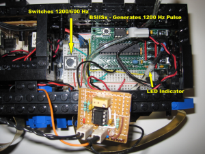
You can also see a close-up of the 555 timer. Some may ask why I did not use a 556 timer. There is no real good reason other than I discovered the 555 first and wanted to have some control over other features of the system. the BSIISx allowed me to integrate with the LCD and provide some other feedback. I have already created a similar beacon circuit using a 556 timer and may swap out for that later once I get more testing done.
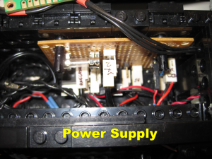
A close-up view of the power supply. It was necessary to provide somewhat clean regulated power to the various components as wall warts are known to be flaky at best. This board contains 2 power regulation circuits. One runs through a LM7809 and a cap to provide regulated 9 volts and the other runs through a LM7805 and a cap to provide regulated 5 volts. All components run through this to get their power. At the top left you can also see a fuse. This is the direct line that runs from the wall wart power to the charge bars. The power for these is unregulated as the NXT LiIon battery charger takes care of this. It was necessary to fuse this in the event that the charge bars were shorted.
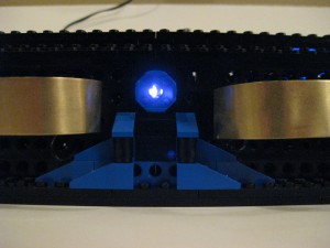
A front view of the beacon when powered. The camera shows the beacon IR LEDs illuminated. These LEDs are being driven at 1200Hz with a a 38KHz carrier. Tuned for the HT Ir Seeker V2. When Pulito needs to charge, it seeks out this beacon source and navigates towards it. It was necessary to cover the cylinder with the axle holed plate as the 3 IR LEDs flooded the area with IR and made it more difficult for Pulito to center itself in the beacon base. This way, the IR light is not as dispersed. This also limits the distance of detection, but this is not an issue in the area that this setup is running within.


Comments: