
Quadcopter – Enhanced Lost Model Alarm
Just 24 hours earlier I built my first Lost Model Alarm. Not being satisfied with good enough, 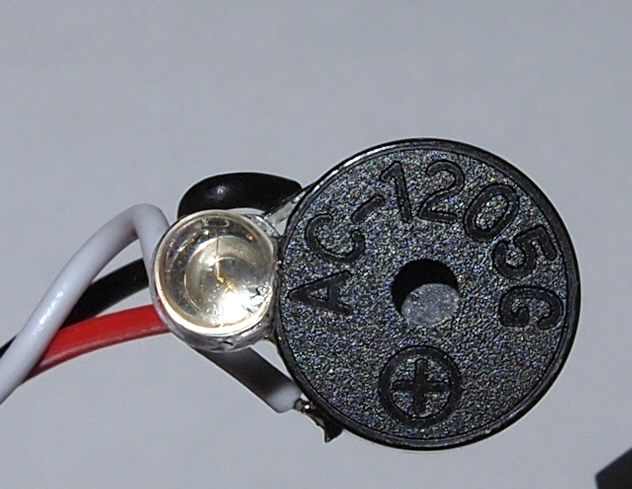 I’ve built an enhanced version. Of course, you could just buy one, but where’s the fun in that?! As mentioned in my original posting, I wanted the alarm to have multiple modes. First, I wanted to be able to have it triggered while the TX is on using one of the available aux controls. Second, I wanted it to always come on if the TX looses power (presumably range). I’ve managed to figure out how to do this using the Turnigy 9x Pit Trim pot (Aux 2).
Update: Sept 2015: Check out my latest post on how to install and configure this alarm with Flip32 and Cleanflight.
Parts:
- ATTiny85 (An 84 or even 25 may work as well)
- Piezo buzzer (5V or higher)
- 100 Ohm resistor
- LED (blue was used here – range is about 2.5 – 3.5v)
- Servo lead wire

Update (Sept 2105)
I’ve since modified the Arduino code and setup for this to simplify it as an on/off alarm controlled by an Aux switch. Check this out for more info.
Tx Set-up:
The Turnigy 9x Ch7 is configured to Pit Trim – which is Aux 2. Also note that you may have to reverse the channel if your values appear opposite when testing (see Tips below). To do this, navigate to the settings > Reverse section in your TX and reverse Aux 2. You can also see the trimpot change if you go to Display > Settings. When turned all the way CCW, the bar should appear filled to the right, and vise-versa as you turn it CW.
Improvements over the original alarm:
- I wanted to keep the AtTiny85 pins exposed for future updates.
- I also added an 100 Ohm resistor inline as the LED only needs about 2.5v.
- Set my Turnigy TX Ch7 using the Pit Trim (Aux 2). The values for Pit Trim range from 1043 (all the way CCW) to 1867 (all the way CW)
- The code watches the PPM signal and reacts as follows:
- If the TX is switched off (value falls to 0), trigger the alarm. For the Arduino code, I just look for any value less than 50 (this allows for some buffer).
- If the trimpot is turned up all the way CW, trigger the alarm. I also wanted to change the tone and beep rate depending on how high I turn the trimpot. The Arduino code does this by reacting for any value above 1500, and will trigger the faster beep above 1700 and slower beep above 1500.
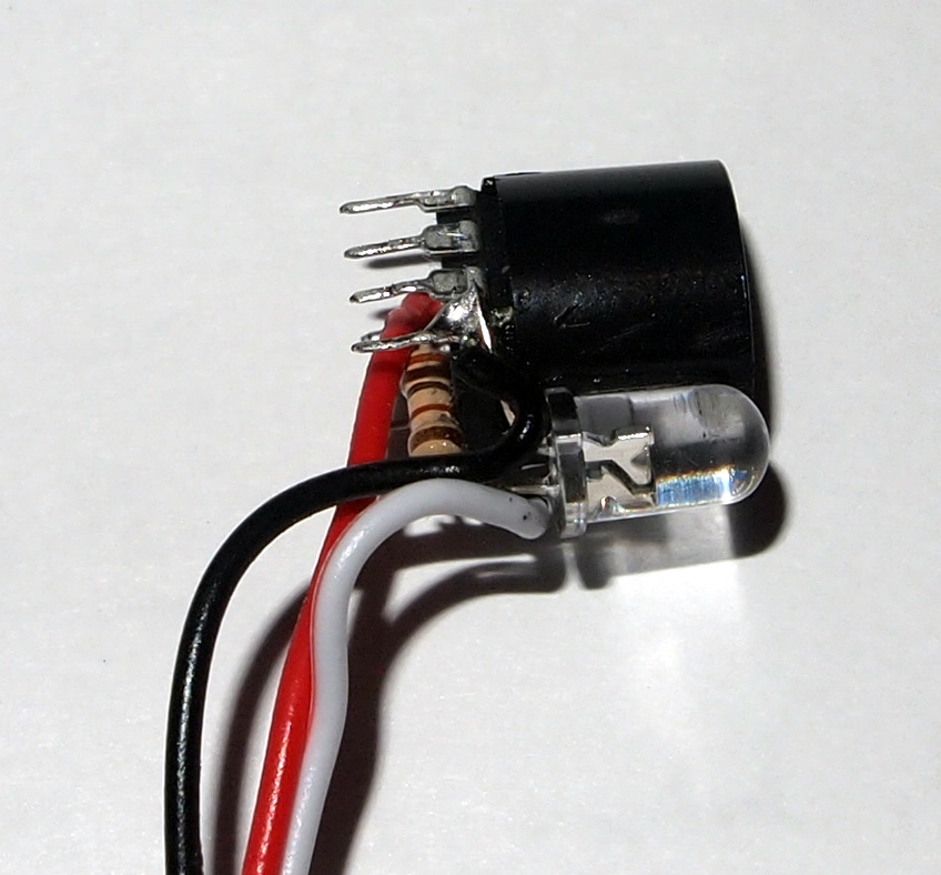 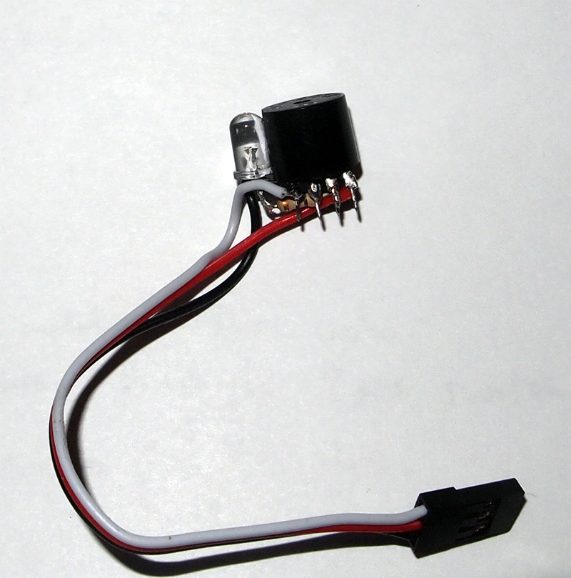 |
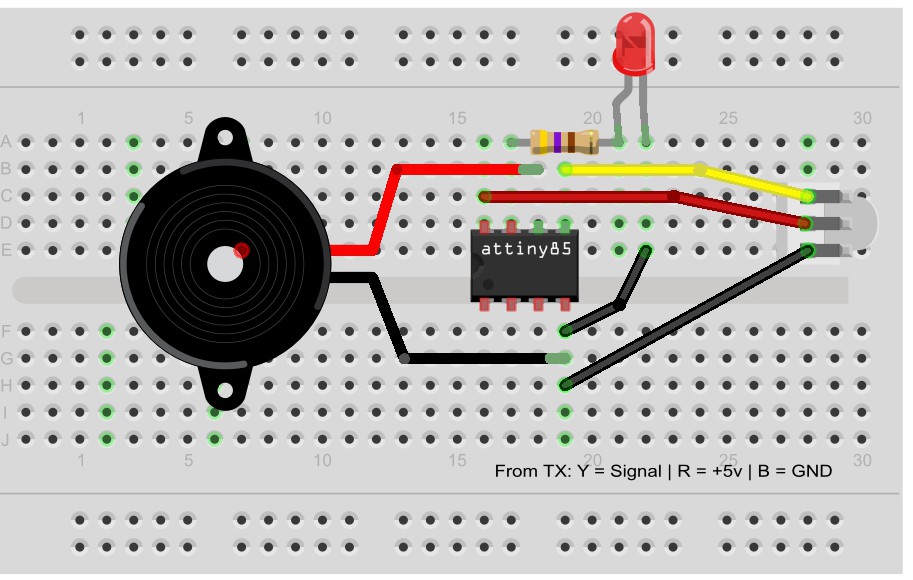
Wiring it up:
This should be pretty easy if you have basic soldering skills. The pins are somewhat close, but with a little patience you should be fine. The AtTiny85 pins number from 1 – 8 with Pin 1 being identified by the dot on the top of the IC. Solder the piezo, LED and servo wire GND to pin 4. In the images above you can see how I set the Tiny in the base of the piezo. It fit perfectly, and you can even glue it in there. Next, solder the servo wire white (shown as yellow below) to pin 5, then the piezo “+” to pin 6. Solder the 100 Ohm resistor to the “+” of the LED, then solder the other end to pin 7 on the Tiny. You’re done.
Programming the circuit:
This is where things can get a little tricky as you have to program the ATTiny. There are plenty of instructions out there, if you Google it. This one works. Essentially, you use an Arduino Uno (or other) set as a programmer and then connect the Tiny to the Arduino, select the ATTiny85 board (usually 8MHz) and download the code. Once you have successfully done this, don’t connect it to your model just yet. You don’t want to fry the thing if you connected something wrong. If you are confident the code downloaded successfully, connect the servo lead to a 5V power source (just the red and black wires). If the code downloaded, you should hear the piezo beeping and see the LED light. Essentially, the code that looks for a value < 50 is triggering as there is no input on the signal line. This is simulating the same thing as the Tx power being lost. If it did not work, first check your soldering. If that is fine, your code may not have downloaded successfully. Go get a beer, come back in 5 minutes and try programming it again. You need to ensure that your Tiny successfully takes the code. I also suggest you Google some programmer image samples to see the variety of programmer set-up’s out there. I use this one.
Tips:
You can use the same code below to read the PPM values from your receiver. Simply uncomment the Serial.print lines and remove the rest of the logic. Connect your RX signal pin to the pin identified for RcPin (0 on the ATTiny below) and the RX black wire to GND on your Ardiuno. This assumes you have your Arduino connected to your PC/Mac, so don’t connect the red (5v) wire coming out of your RX to anything. Run the below sketch, open the serial window and watch the values being returned as you turn the trim knob. If they are not changing you need to check to ensure you have the right channel configured on your TX and you are plugged into the same channel on your RX. Also ensure you power up your Quad Rx.
Enhancements:
Having a range of values from a trimpot gives you a plethora of control options using a single channel. Ideas:
- You could configure the below code to trigger an external more powerful alarm when the PPM value is in a specific range (i.e. 1800 – 1850).
- Have it trigger a high intensity LED powered off the main battery pack using a transistor to switch the LED or blink it.
- Use the trimpot ranges to trigger different activities. For example, you could still have the alarm trigger when the Tx looses power (value = 0) and have a multi-coloured LED light strip that changes colours depending on values greater than 0.
Arduino Sketch:
Download: QuadRemoteSwitchIntercept.ino
//ATTiny85  - pinouts are here http://highlowtech.org/wp-content/uploads/2011/10/ATtiny45-85.png
//pin #1 has the black dot on the chip.
// 1      8
// 2      7
// 3      6
// 4      5


int rcPin = 0;     // PWM signal in from RC receiver - connect to Pin 5 (see above)
int buzzerPin = 1;  //Buzzer pin out to buzzer  - connect to Pin 6 (see above)
int ledPin = 2;     //Optional - connect to Pin 6 (see above)
int chPWMVal = 0;        // Receiver channel pwm value - connect to a free channel on your RX. Leave value at 0.

void setup() {
  pinMode(rcPin, INPUT);
  pinMode(buzzerPin, OUTPUT);
  pinMode(ledPin, OUTPUT);
  //Serial.begin(9600);  //for debugging
}

void loop() {
  // Read in the length of the signal in microseconds
  chPWMVal = pulseIn(rcPin, HIGH, 25000);
  digitalWrite(ledPin, LOW);   // turn the LED on (HIGH is the voltage level)
  //Serial.print("Channel #: ");
  //Serial.println(chPWMVal);

  //Logic is based on Turnigy 9x Pt Trim configured on Aux 5.
  //When turned all the way CCW values read ~1043
  //When turned all the way CW value read ~1867
  //When the TX is turned off or looses range, the value drops to 0.
  //Based on this, trigger the alarm if the value is above 1500 or below 50 (allows some bias)
  //This will allow the alarm to be triggered in 2 situations:
  //a) when the TX is turned off
  //b) when the Pit Trim pot is turned all the way CW - this allows the TX to remain on while the alarm is being sounded.

  if ((chPWMVal > 1500) || (chPWMVal < 50))
  {
    if (chPWMVal > 1700)
    {
      digitalWrite(ledPin, HIGH);   // turn the LED on (HIGH is the voltage level)
      tone(buzzerPin, 2800, 300);
      delay(300);
      digitalWrite(ledPin, LOW);    // turn the LED off by making the voltage LOW
      delay(200);
    }
    else
    {
      digitalWrite(ledPin, HIGH);   // turn the LED on (HIGH is the voltage level)
      tone(buzzerPin, 3000, 300);
      delay(800);
      digitalWrite(ledPin, LOW);    // turn the LED off by making the voltage LOW
      delay(200);
    }
  }
}


Comments: