
Make your Ninebot Max Dazzle with these DIY NeoPixel LEDs
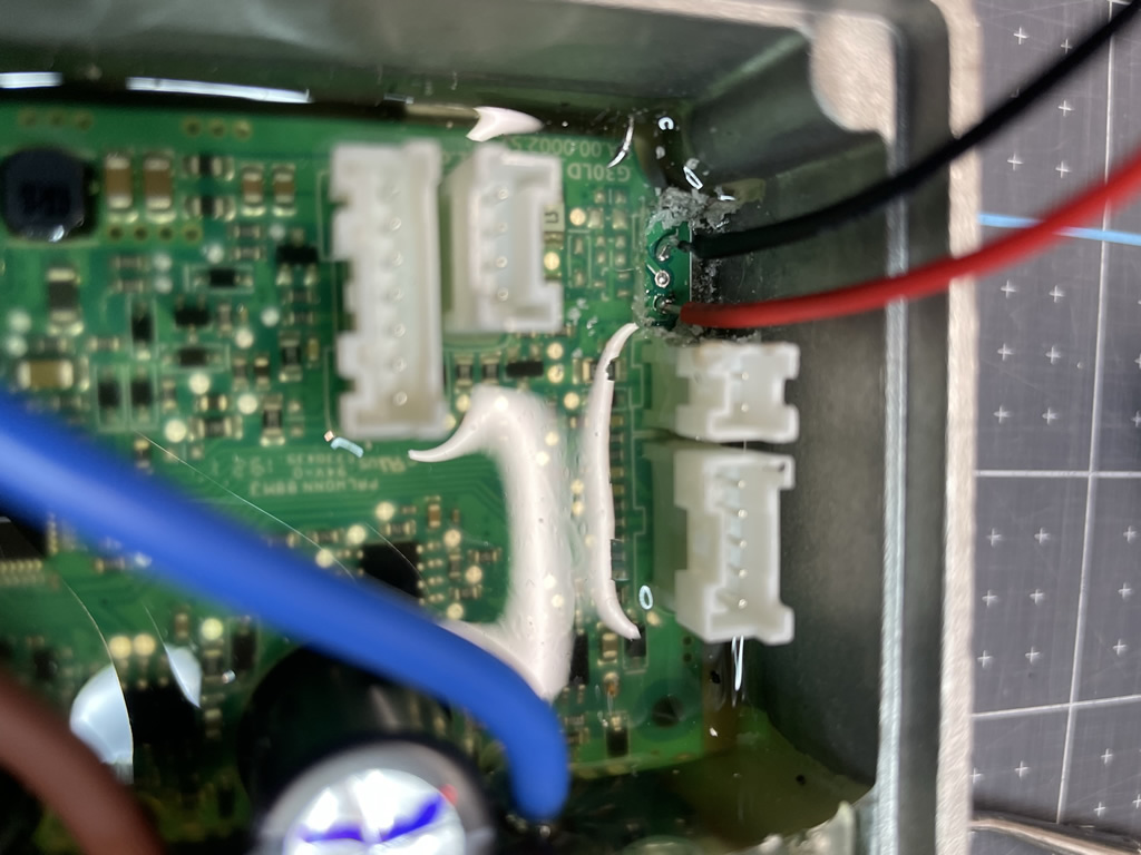
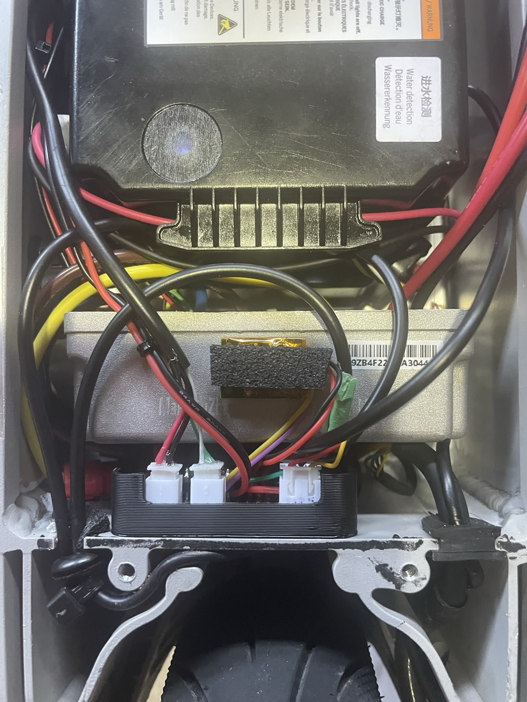
Having an interest in all things “hackable”, I recently got into the e-scooter game. I managed to find a Ninebot Max G30LP on FB on the cheap that had some issues – namely the rear tire needed replacing, the steerer tube was loose and needed some JB weld, and the motor controller wires had nearly melted through. Yikes! Lucky looking at the guts of this thing was the first thing I did. I replaced them with these massive XT150 connectors (yes a bit overkill). BTW this is a well known common problem on Ninebot Max’s, so if you have one, you NEED to check this ASAP. If it fails, you will be lucky if it just fry’s your controller and doesn’t start a fire! That’s my safety moment of the day!
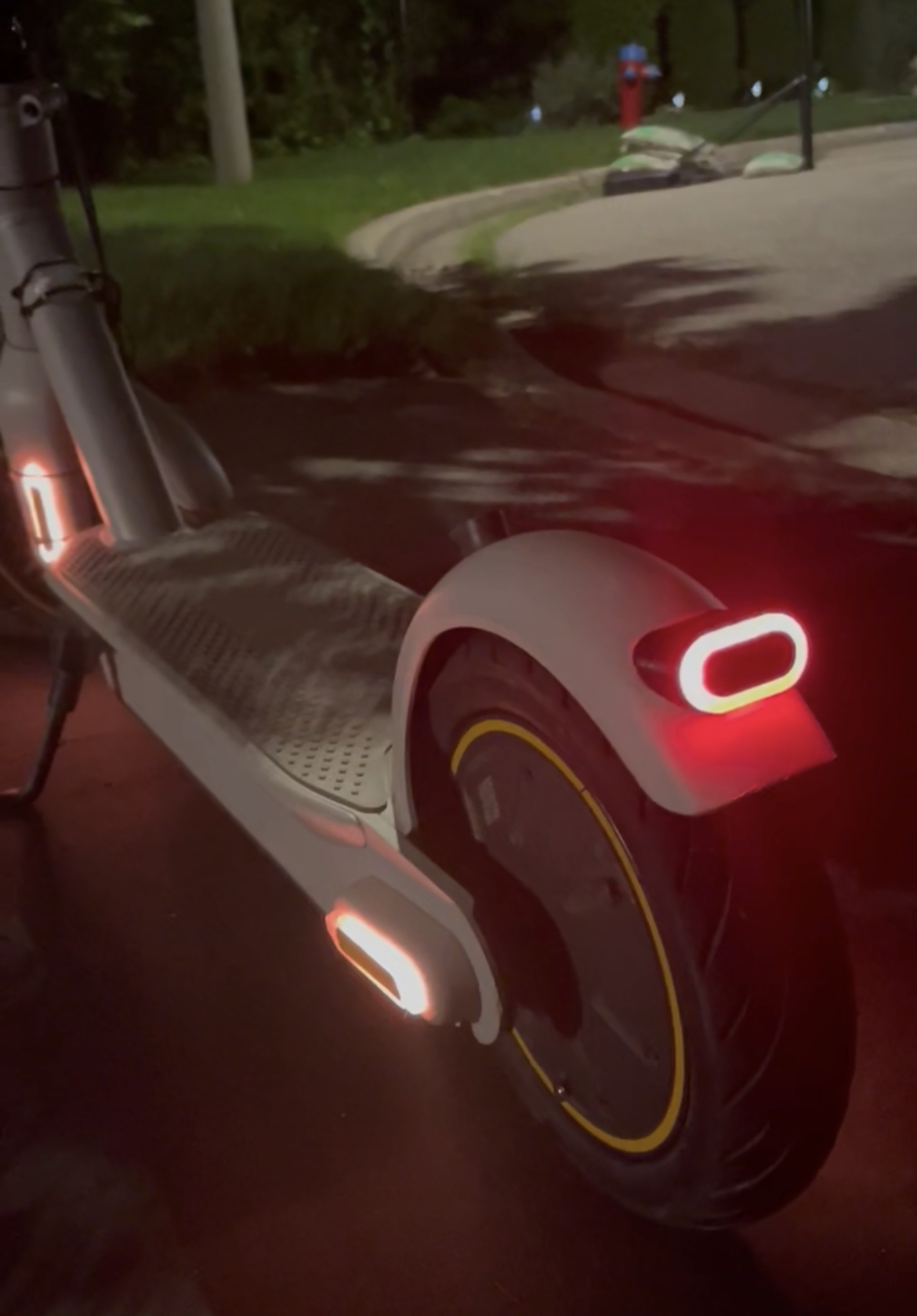
Anyway, the point of this post is to show my custom DIY LED NeoPixel mod. TLDR – I took a micro controller plus a gyro, light sensor, and NeoPixel LEDs and wired it to the main controller board to allow custom lighting for the side markers and rear tail light.

Details:
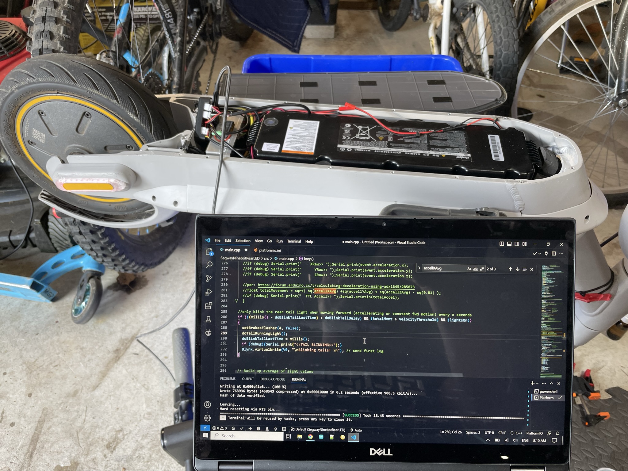
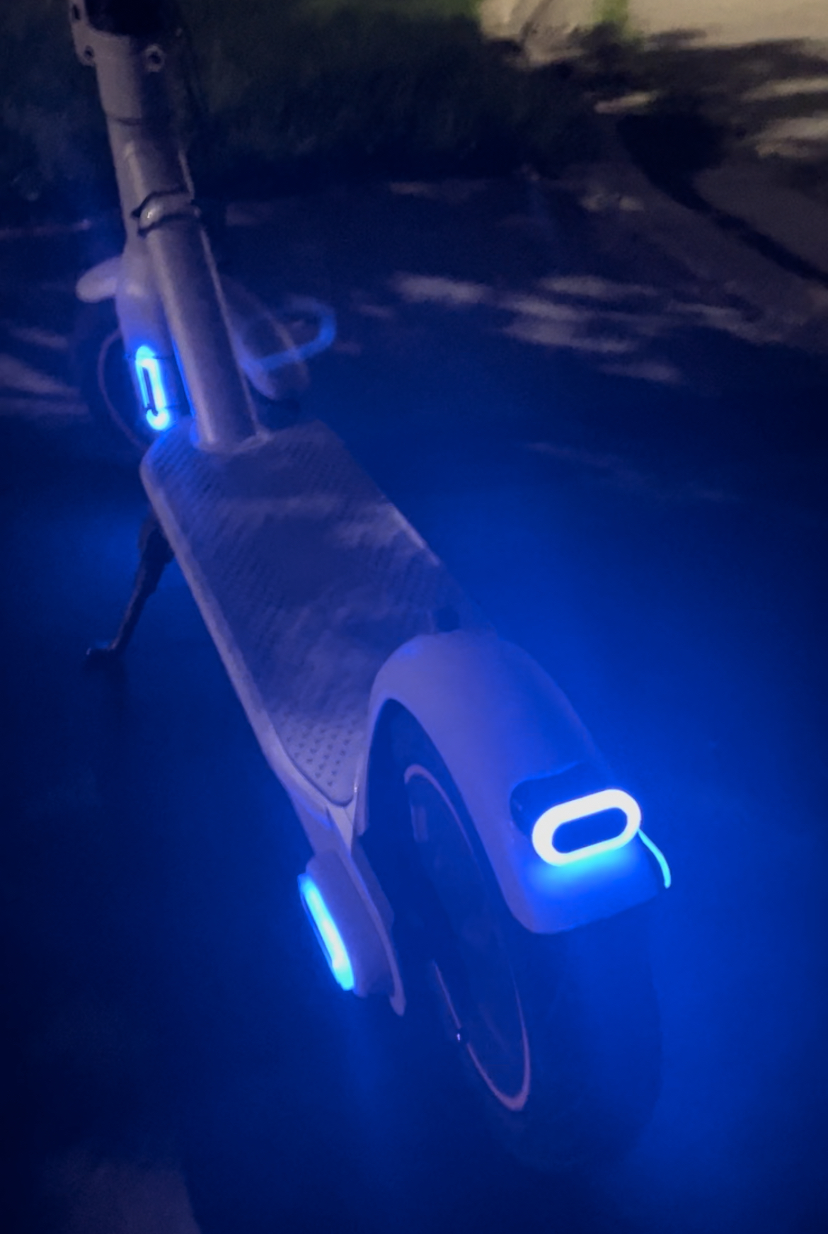
The use case for this sucker is pretty straight forward. On startup, all LED strips ramp up to glow blue, then after about 15 seconds, the sidemarkers fade to orange, and rear tail fails to… yep red. A light sensor monitors the ambient light level outside and dims the LEDs down during the day so they are vaguely visible, then when it hits a “dark” threshold, they ramp up to near max brightness. This can easily be modified to whatever you want. There’s also some averaging and time logic there so the LEDs don’t turn on/off with car or street lights. The gyro is there with the intent to monitor movement and trigger the rear taillight to blink while moving, but just be “on” when stopped. The interesting thing about gyro’s is they detect velocity (not movement per-se). It changes more-so when there is acceleration (+/-) along an axis. However, once a constant speed is reached, the values drop to near 0, which makes it hard to detect movement in general. I’m not a math guy, so I found a sample that uses some math stuff with all 3 axis to aim to report movement. e.g. Z would “feel” the bumps, Y would feel the cornering/or swaying back-and-forth, and X would monitor forward motion. Admittedly I rushed into this part as it’s not yet working as intended as it seems to be triggering all the time, so I need to do more testing to refine the trigger points. Any experts out there, please drop a comment into suggested code to correctly monitor movement (not just accel/decel). That said, I don’t mind the current function as the tail is always blinking when in the dark mode.
Compatibility:
The “fit” of this project and components is really about 3 main things:
- Finding a 5V power source (which most controllers have). This is the only interface to the Ninebot – power.
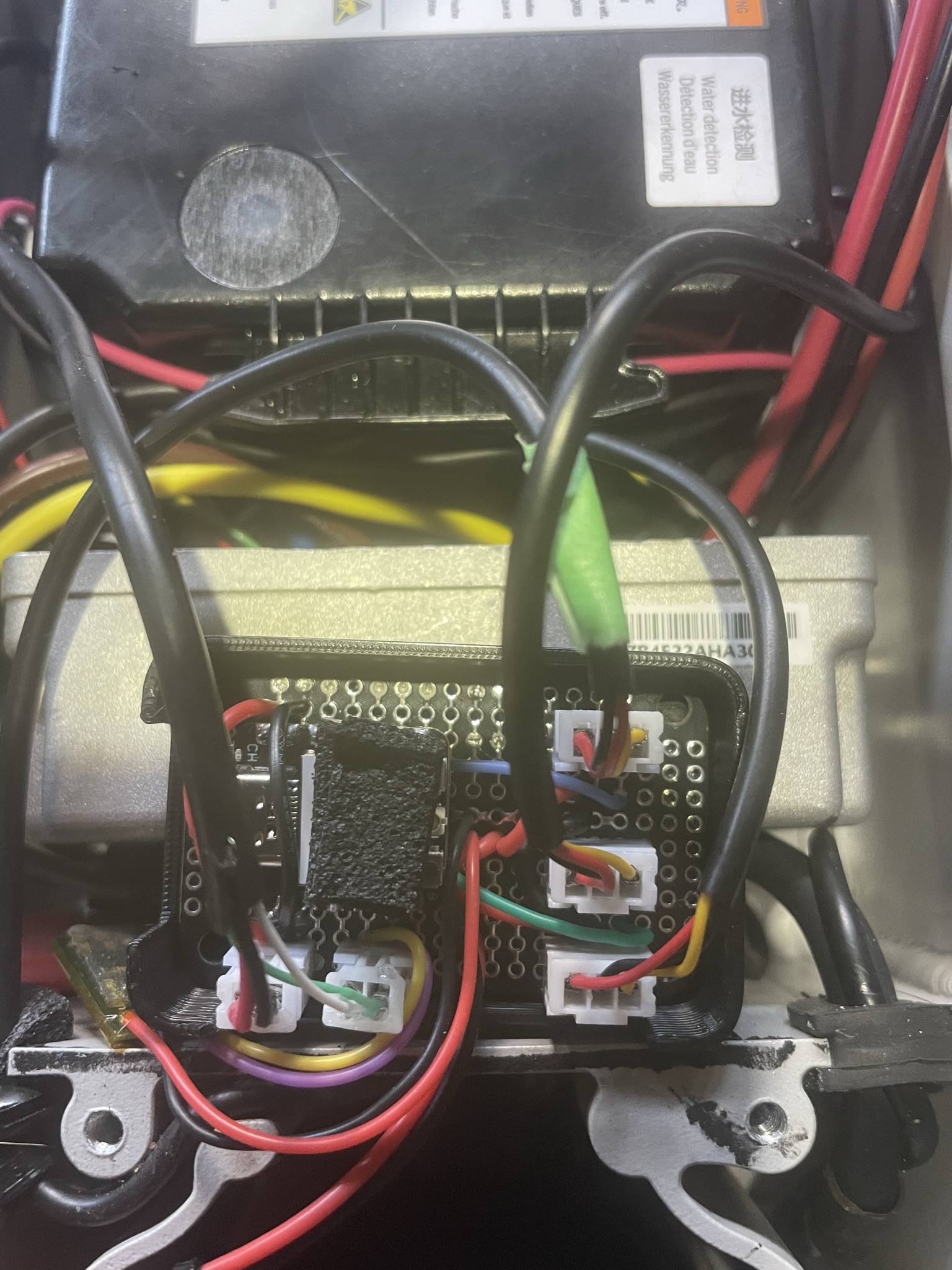
- Space: There must be room somewhere in the battery compartment for the controller and wiring (preferably closer to the back)
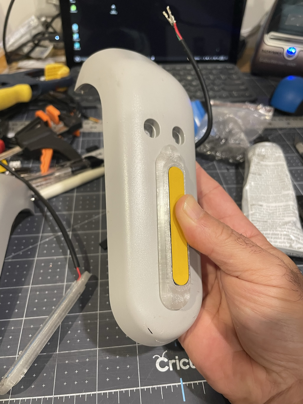
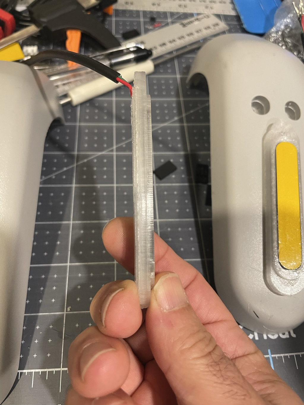
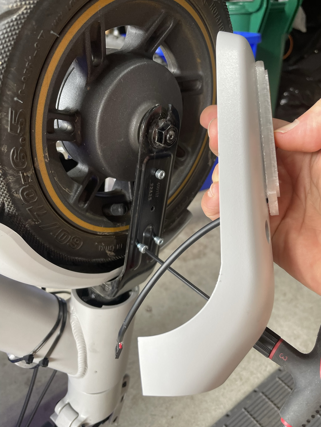
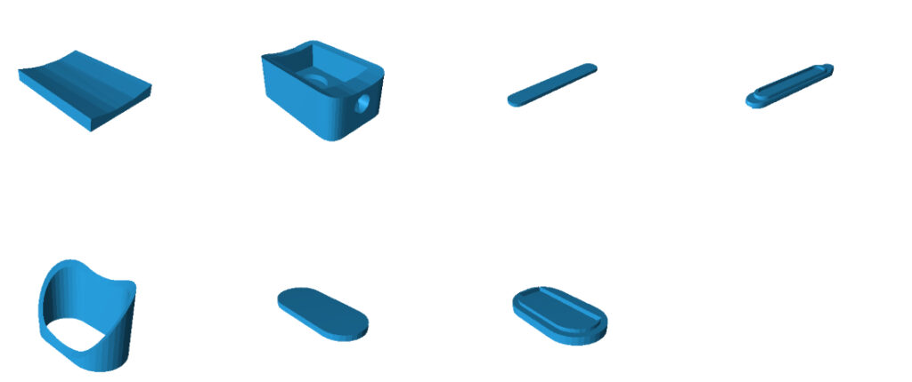
- LED Lenses: The 3D models are sized for fitting onto the front and rear plastic bolt covers. I think these are the same across Ninebot Max models, but can’t be sure. That said, you can 3D model whatever you want if you have the resources and printer. The rear LED should be a universal fit for the fender but assumes you remove or ignore the stock LED.
Controller & Build:
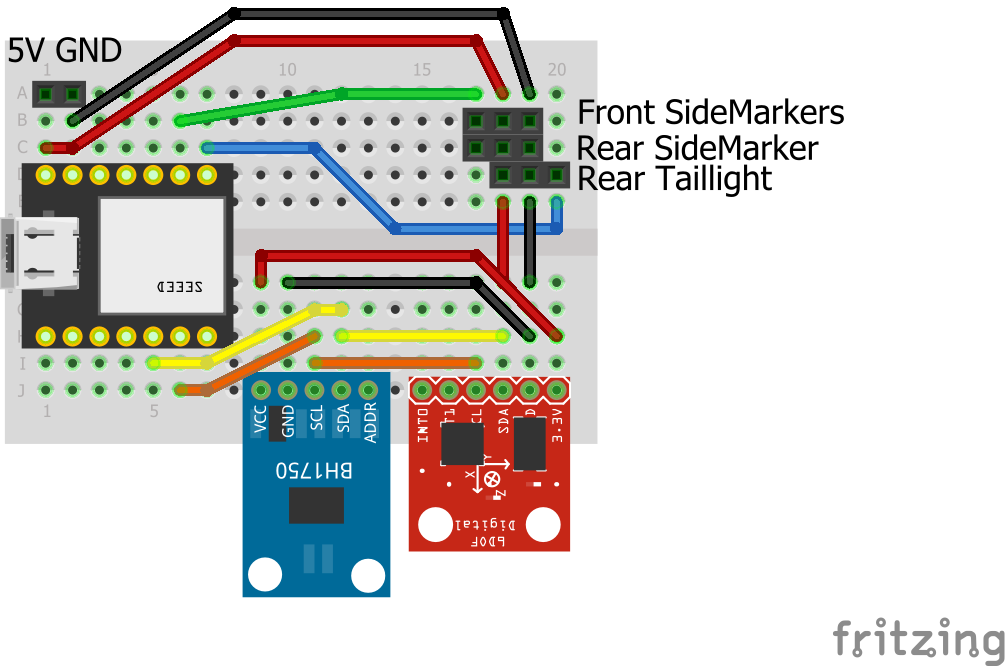
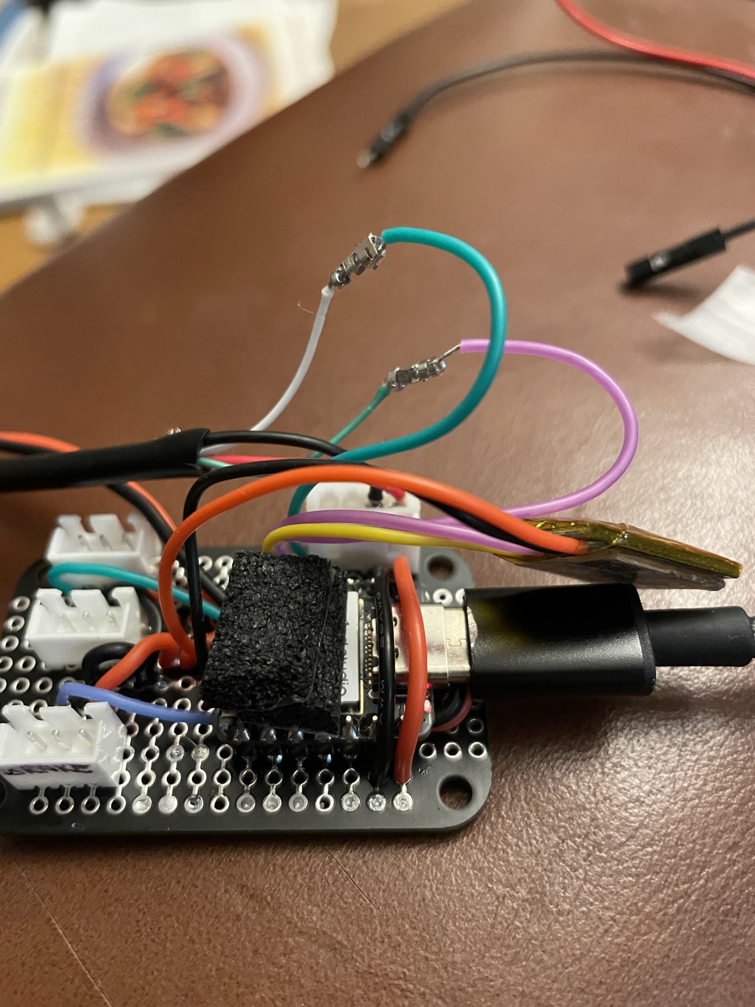
This one should be an easy build for most folks. The MCU is a SEEED XIAO ESP32C3. It’s connected to 5V/GND in the Ninebot controller (see gallery pics below). The LED NeoPixel strips are wired as follows: The front/rear sidemarkers are wired to the one data pin but have 2 connector as shown. One for the front 2, and one for the back units. This could also be done with 1 connector but there would be a lot of “Y” splitting going on there. The Rear taillight has it’s own connector. Both the light sensor (BH1750) and Gyro (ADXL345) are wired to 5V/GND on the breadboard and tie into the SCL / SDA data pins on the XIAO (pinout).
Regarding the LED strips and mounting in general. In all cases, I use my go-to glue (Amazing Goop). The LED strips, lens mounting etc are all glued using this stuff. It’s strong, yet easy to remove. Important for the cases of the side markers which are mounted over top of the screw holes on the Max.
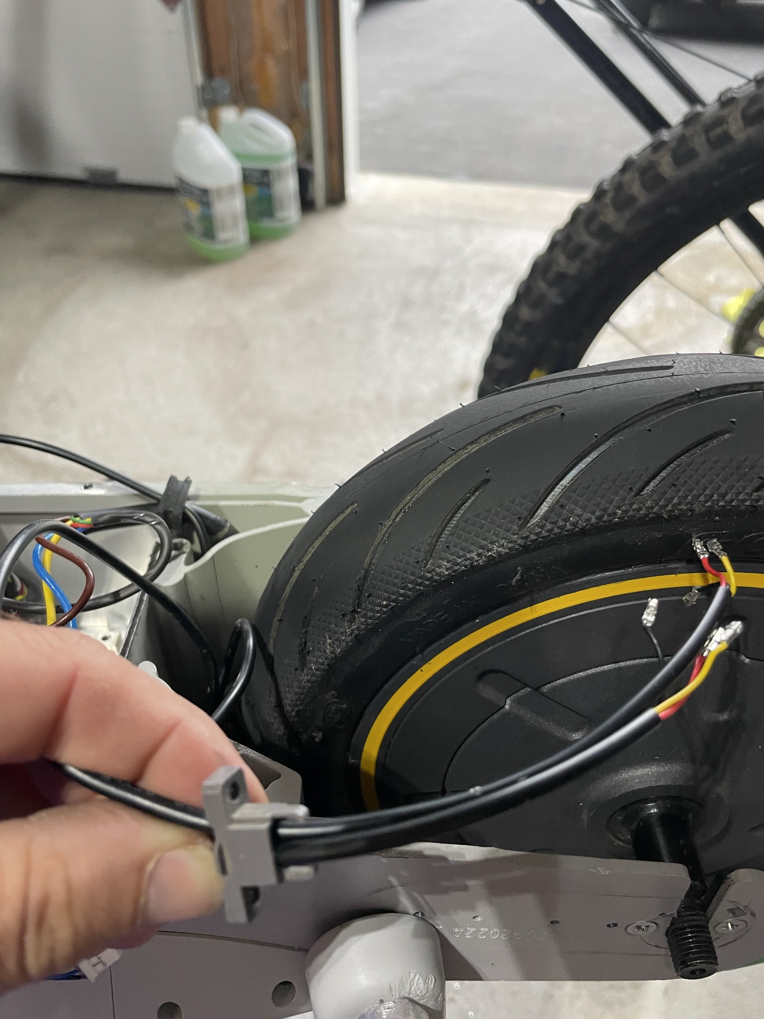
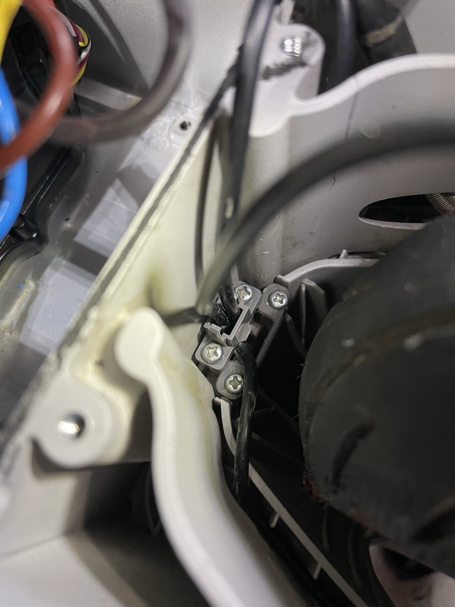
Wire Runs:
The Ninebot offers some nice options to run the wiring for the LEDs. Have a look at the gallery pictures to get an idea there. For the rear markers, I had to drill a tiny hole in each side to run them to the cover place. Note that the 3D lens for these have to be glued on after the covers and when are re-mounted. Yes, counter-intuitive, but I don’t expect to remove these anytime soon, and the glue I use is easily removed and re-applied. For the front markers, the wire runs along the battery to the front, steerer tube and out the side. There is lots of space for this.
Next Steps:
- Enable OTA. As it’s a pain to access the controller, I am planning to add the over-the-air (OTA) firmware download option so I can more easily change features in the future.
- LED Modes – the current modes shown are cool, but I may enable blinking on the side markers. Also want to refine the accelerometer settings for this as well.
- Brake Lever – This is my biggest pain point of the Max. The lever is too big/long and reach is too far for my liking. Coming from a MTB world using XTR hydraulics for years, I plan in changing out the stock lever for something similar in size (but mechanical). The challenge will be that I need to re-create the Hall sensor function for dynamic braking. Build and testing info will be linked here at a later time.
Parts List:
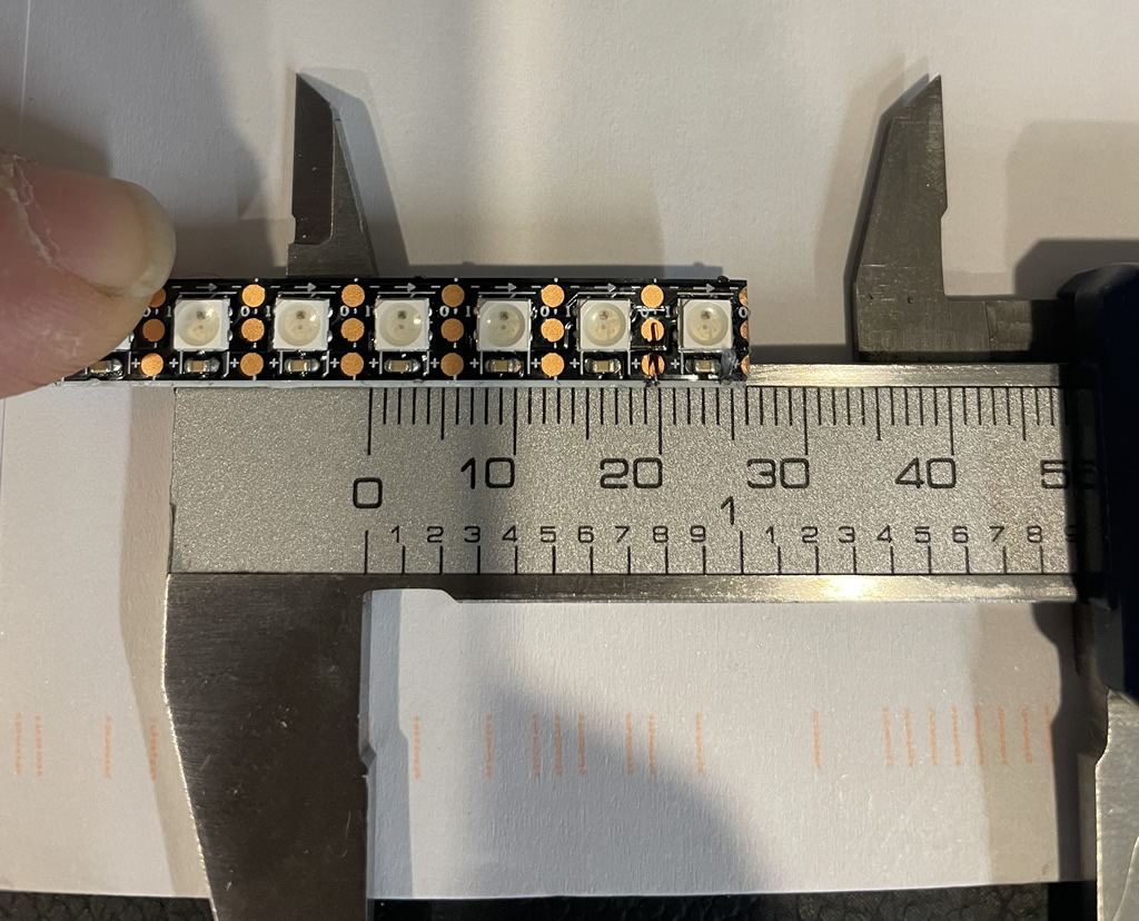
- 5V NeoPixel Strips (144/meter) I used the smaller sized WS2812 type. LED sizes are about 3.5mm x 3.5mm so small. See gallery images for sizing.
- SEEED XIAO ESP32 (but XIAO models will work as well)
- BH1750 Light Sensor
- ADXL 345 Accelerometer
- Various headers, wires (I recommend these silicone wires)
- 3D Printed parts can be found on my Thingiverse Page
Your Support is Appreciated: A lot of time is put into designing and building these projects, the creation and editing of videos and pulling together my build logs. If you find this useful, please consider a small donation – buy me a coffee as they say 🙂 It will go to purchasing new items/components for future projects and help support the work I do here. You can support me either via Ko-Fi or Paypal below. Additionally, clicking the above product/part links also helps and it costs you nothing. Thanks!
Usage & Code: Please see my Disclaimer page.
This code is Arduino-based but used within the Platform.io framework. If you use it, you already know what to do. If you want to use this in the Arduino IDE, simply rename to .ino and place in a folder with the same name (less the .ino). The board info is in platform.ini. Please make sure you respect the licensing rights noted.

Share code plz… COOL project!