
LulzBot Mini: LED Lighting Controller
Update: Check out the more recent mod – camera mount and better lighting.
So, I just got my LulzBot Mini this week and have to say I love this thing. It’s my 2nd 3D printer (I Kickstarted the M3D – but it was not a reliable machine). Anyway, like any guy with a new toy, I had to do something to make it my own! ..and why not print some parts for it!
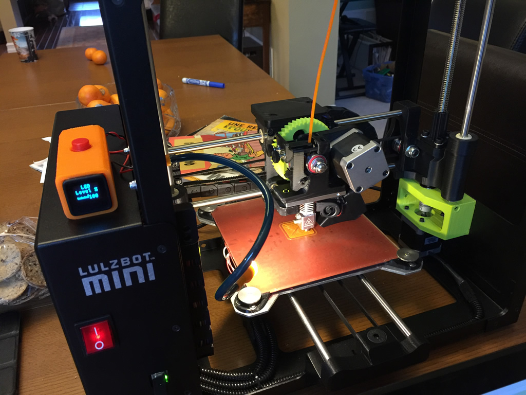
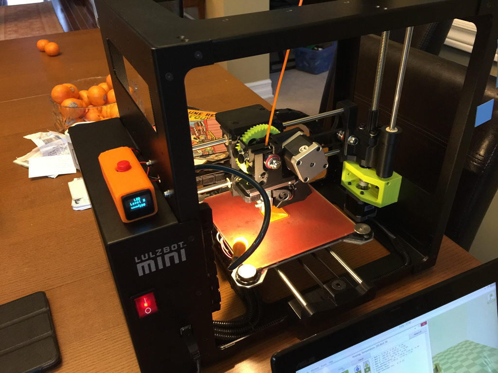
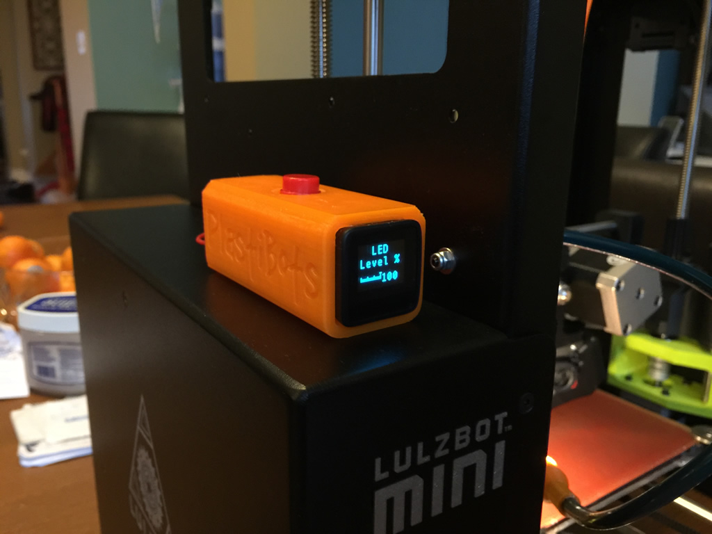
The final resting spot for the Mini does not have very good lighting. I wanted to build a flexible LED light that could be dimmed, and turned on/off when necessary. I also wanted to just turn it on, and leave it knowing it would go off after a pre-set period of time (e.g. 1 minute). I had a spare MicroView laying around and thought it would be cool to be able to visualize the LED settings as well. It will also allow for future features I have yet to dream up. (details and parts below).

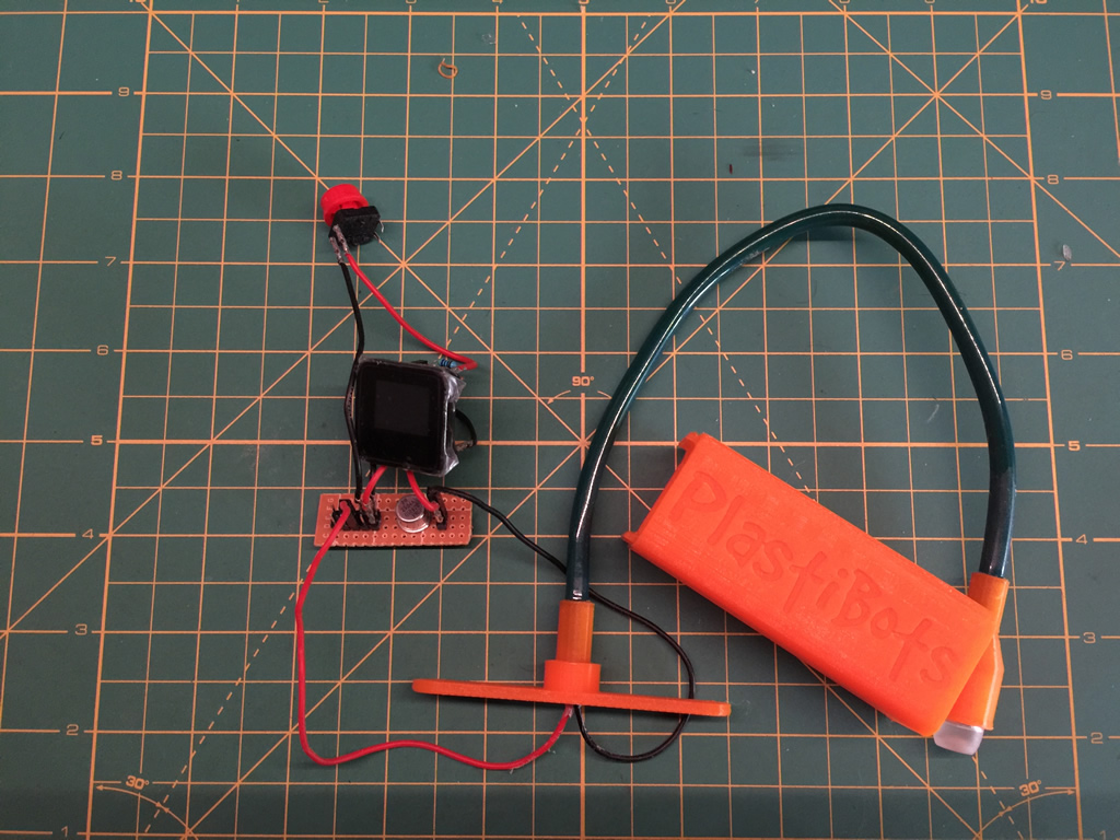
Parts:
- Sparkfun MicroView.
- 2n2904 Transistor
- Push Button Switch
- Adjustable Switching Regulator
- G4 1W 12V 60 Lumen LED
- Switching Mode Variable Voltage Regulator (takes 24V down to 12V)
- Flexible Micro Sprinkler (has casing + copper to make a great flex arm)
- Printed casings / parts – PlastiBots on Thingiverse
The Details:
Power is sourced directly from the LulzBot 24V DC output. I tapped off the +/- that was connected to the heated bed input on the Mini Rambo board (but I don’t think it matters). The regulator was set to 12V and was connected to both the MicroView (yup it can take 12V) and the LED (via the 2n2904). A PWM pin on the MicroView triggers PWM output into the 2n2904 that then controls the brightness of the LED. The switch is connected to Pin2 as an input and is used to control the LED levels. I used the built-in MicroView graphic bar widget to show the light level.
Future Ideas:
I don’t yet know the RAMBO board but given it is Arduino-based, I would expect some sort of serial output. Potentially being able to get a real-time output of status such as GCode line #, or temperature values etc.
The Code:
/*
Using a MicroView. Board should be Arduino Uno
*/
#include <MicroView.h>
MicroViewWidget *widget[1]; // declaring an array of 4 MicroViewWidget
int pushBotton = 2;
//PIN 6 will be Tip31 base output pin. PWM out AnalogWrite
int LEDpin = 5;
//int iVal = 0; //input value for pushbutton
int level = 0;
int buttonState; // the current reading from the input pin
int lastButtonState = LOW; // the previous reading from the input pin
long lastDebounceTime = 0; // the last time the output pin was toggled
long debounceDelay = 150; // the debounce time; increase if the output flickers
void setup() {
pinMode(LEDpin, OUTPUT);
uView.begin(); // init and start MicroView
widget[0] = new MicroViewSlider(0,35,0,100); // declare widget0 as a Slider at x=0, y=0, min=0, max=100
//widget[1] = new MicroViewGauge(32,24,0,255,WIDGETSTYLE0); // declare widget0 as a Slider at x=0, y=10, min=0, max=150
uView.clear(PAGE); // erase the memory buffer, when next uView.display() is called, the OLED will be cleared.
analogWrite(LEDpin,255); //ensure the LED is off at startup.
}
void loop() {
//analogWrite(LEDpin, 0);
//delay(500);
//analogWrite(LEDpin, 255);
//delay(500);
int reading = digitalRead(pushBotton);
// If the switch changed, due to noise or pressing:
if (buttonState != lastButtonState) {
// reset the debouncing timer
lastDebounceTime = millis();
}
if ((millis() – lastDebounceTime) > debounceDelay) {
// whatever the reading is at, it’s been there for longer
// than the debounce delay, so take it as the actual current state:
// if the button state has changed:
if (reading != buttonState) {
buttonState = reading;
// only toggle the LED if the new button state is HIGH
if (buttonState == HIGH) {
//ledState = !ledState;
changeLevel();
analogWrite(LEDpin, map(level, 0, 100, 255, 0));
}
}
}
uView.setFontType(1);
uView.setCursor(0,0);
uView.print(” LED”);
uView.setCursor(0,15);
uView.print(“Level %”);
widget[0]->setValue(level);
widget[0]->reDraw();
uView.display();
uView.clear(PAGE);
delay(100);
lastButtonState = reading;
}
void changeLevel()
{
if (level <= 3)
{
level = 100;
}
else
{
level-=33;
if (level < 3) level = 0;
}
}


Comments: