
LulzBot Mini 2: Fan & Lighting Controller
I was so impressed with my Lulzbot Mini 1, that I decided to buy a Mini 2. Holding true to my mantra, whenever I get a new toy, I can’t leave well enough alone. So, I decided to re-create my original Mini 1 custom fan and lighting controller with some tweaks and enhancements for my new Mini 2. Two key drivers were to a) reduce fan noise, and b) add lighting with control.
How it works:
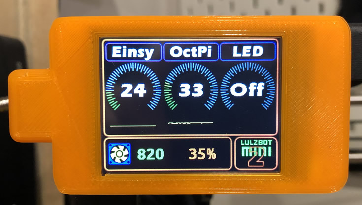
The brain is an Arduino Nano MCU, with Nextion HMI touch screen as an interface, 2 LM35 temperature sensors, a 12V Noctua quiet fan with RPM measurement and 12V LEDs. video below)
Although the Mini 2 made great strides over the Mini 1 in the noise category (the new stepper drivers make a huge difference), both the case and extruder fans are still noisy. On power up the stock case fan is already noisy. Once printing starts it pretty much hits 100% and is on for the duration of the print. So, it had to go. The Nano monitors the temperature of the Eisny and dynamically adjusts the fan speed based on the driver temperature.
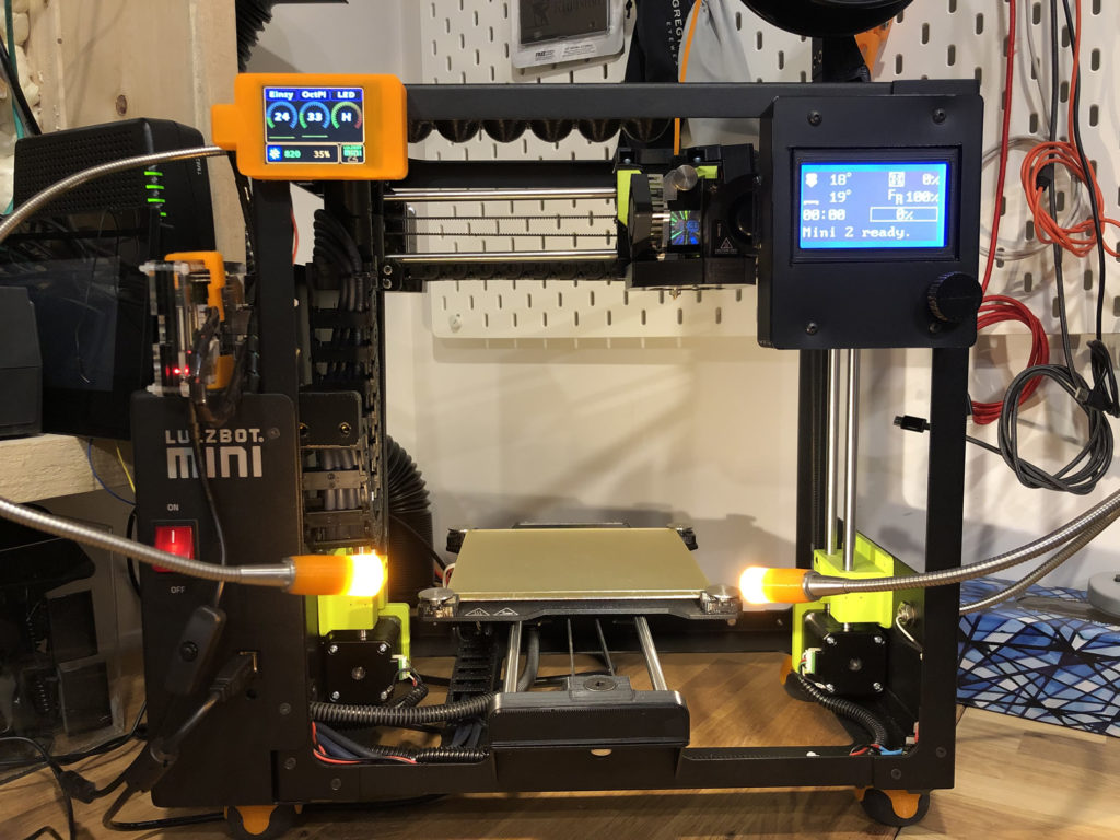
One temperature sensor is mounted to the Y axis driver chip. There is no need to monitor the other axis as the Z driver barely gets warm and the X is much the same as Y. The other temperature sensor monitors the CPU of the Raspberry Pi running OctoPrint. The controller only uses the Mini 2 temperature reading to dynamically control the case fan as that is what counts (and because the Pi is outside). However, an alarm will trigger if either temperature reading goes too high. Tapping the Einsy range meter on the screen will also trigger the case fan to go high. Tapping again turns it back to automatic mode. Have a look at the videos to see it in action.
- Stock with 24V Fan
- With Noctua – Low
- With Noctua – High
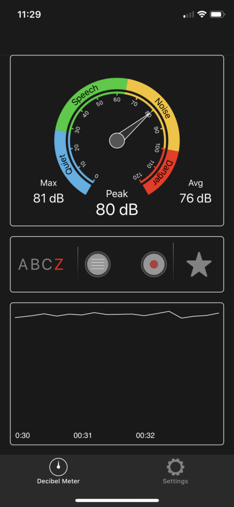
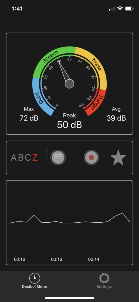

Noise Comparison:
These Noctua fans are worth every penny. As can be seen with the sound meter measurements, there’s a significant drop in noise generated by the case fan. Both in idle mode (~35%) and full on. Also, the fan seldom even hits 100% and tends to stay around 65% as the chips don’t get that hot. It is also sufficient to keep the rest of the components in the case cool.
LED Lighting Control:
The unit also controls the LED lights (2 x 12V) mounted to the printer. Tapping the LED range meter to the right will trigger from High > Medium > Low > Off modes. By default, the LEDs start high when the printer powers up.
Safety:
I like to keep my projects as “un-integrated” as possible. Particularly in this case as I don’t want to introduce interference to the Einsy board which could cause issues printing. It also reduces the risk of frying something on the printer which can be costly. This entire until only has tie-in to the 24V power of the Mini 2. I’m not using any power or fan pins from the Einsy. The fan also comes on by default and based on the way the transistor is configured, the fan takes full (12V) power from the power supply regardless if the Nano is working or not. Essentially, the Nano pulls the transistor base pin Low once powered, else it’s High. So, if the Nano fails, the fan is still cooling the case area.
End Result:
Adding the Noctua fan is a significant improvement in silencing the Mini 2 even more than it’s stock configuration. However, one caveat is the fan on the Aerostruder is now more noticeable. That said, it’s manageable and easier to get used to having only one fan making some noise. Of course the LED control is more of a requirement than a nice-to-have. I was also able to re-use all the parts from the original build on my Mini 1. I had the Nextion kicking around, so cost was only my time. You can build this for less than $60 CAD with the bulk of the cost being the Nextion and the Noctua fan. If you haven’t played around with the Nextion, have a look around my blog for tips and information on the Nextion HMI display. They are powerful and fairly easy to get the hang of. I use them for all my builds now.
Want to build it?
- Arduino Nano MCU
- Nextion 2.4″ HMI TFT
- Buck Converter Power Supply
- Noctua NF-8 Fan (product detail)
- Silicone Wire (suggest 28 and 26 AWG for most connections)
- Buzzer
- 12V LEDs are used in this project. If you use lower voltage LED’s you will have to put a buck converter to the 12V power supply (do not power them off the Nano 5V out as it has very limited current capacity and you will blow the onboard converter).
- PN2222A (transistor LED control),
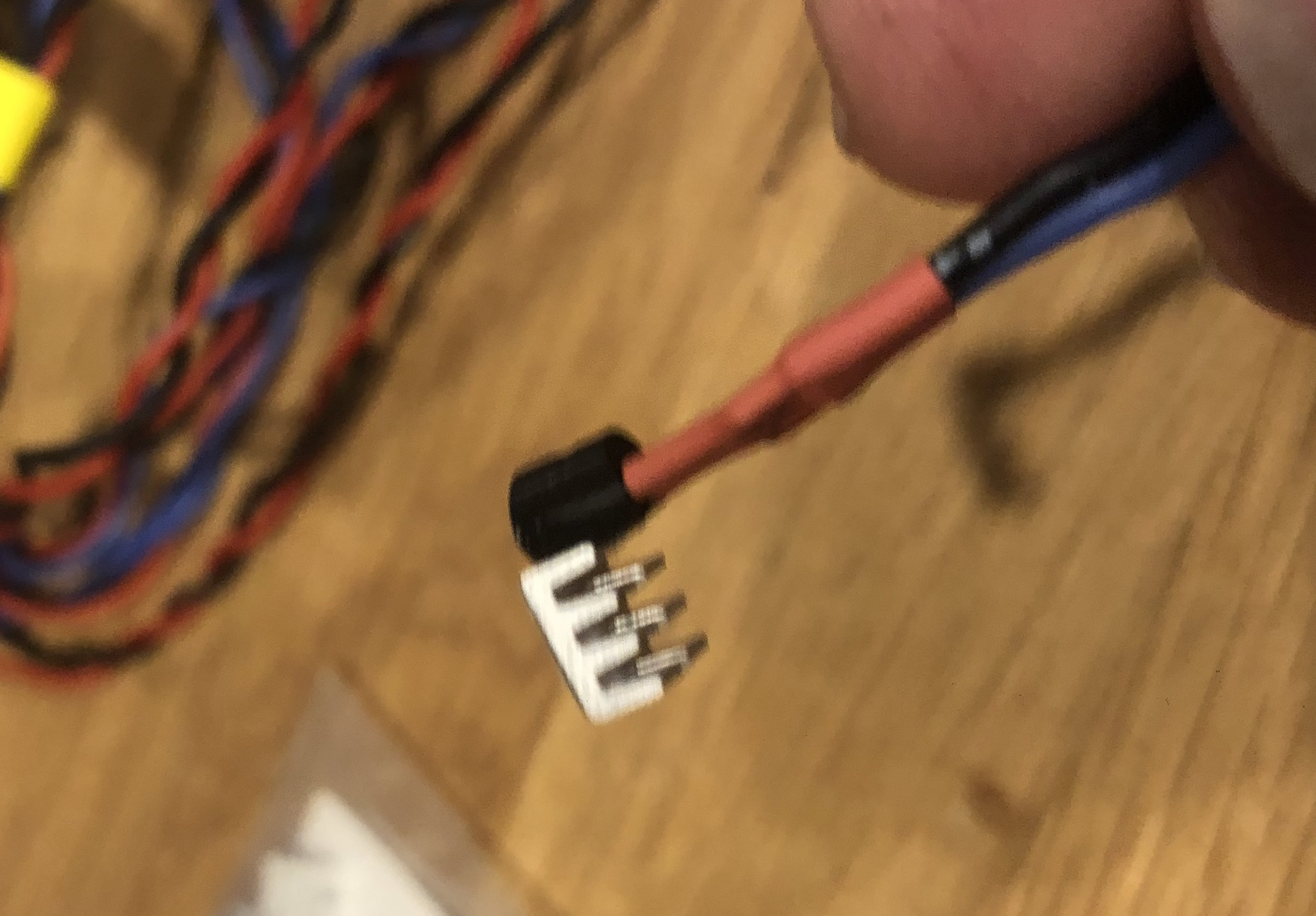
- LM35 Temperature sensor
- Dupont Connectors
- You will need a breadboard, solder etc as well.
- If you are looking for a Raspberry Pi, that cool case in the video or power connector powering my Pi4, check out BuyaPi.ca. They have great prices and fast service.
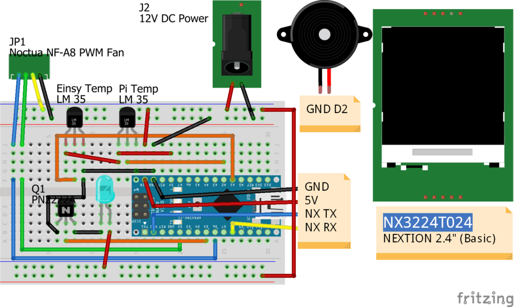
| Nano | ||
| D6 | Fan PWM Control | Fan 12V / GND to power supply |
| D2 | Fan Hall Sensor | |
| A1 | Pi LM35 Out Pin | LM 35 5V & GND |
| A2 | Mini LM35 Out Pin | LM 35 5V & GND |
| LED signal pin | LED’s Transistor to 12V / GND power supply | |
| D7 | Beeper pin | Beeper GND |
| D2 RXD | To Nextion TX | |
| D8 | To Nextion RX | |
| 5V | To Nextion 5V | GND to power supply. |
Code & Usage:
Please see my Disclaimer page. A lot of time goes into making and documenting these projects on my blog. Of course there are also costs involved. I use support funds toward future ideas & projects that I blog about here and share with others. Please consider supporting me at Ko-Fi or PayPal below.
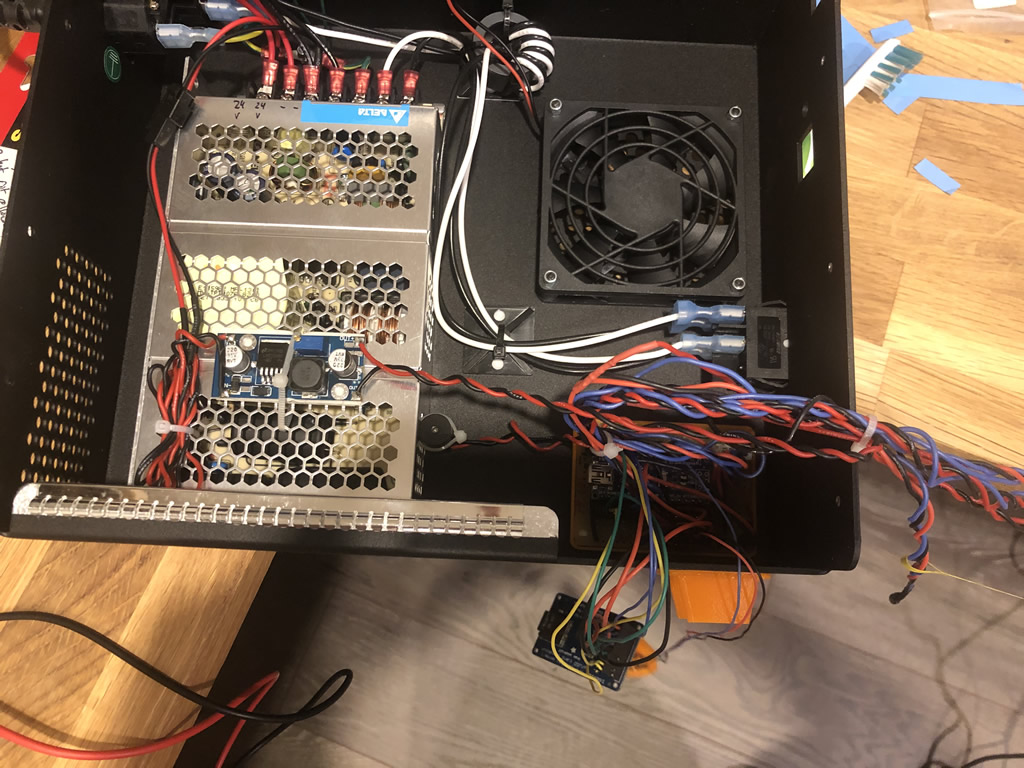
Case Innards 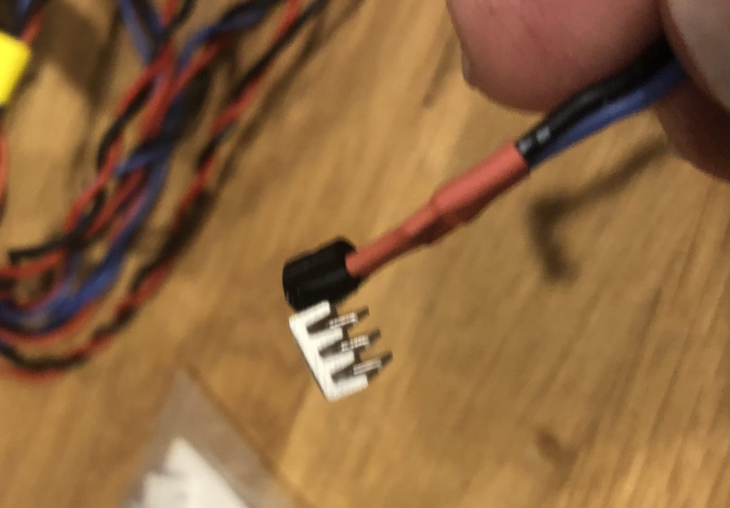
LM35 Glued to heatsink 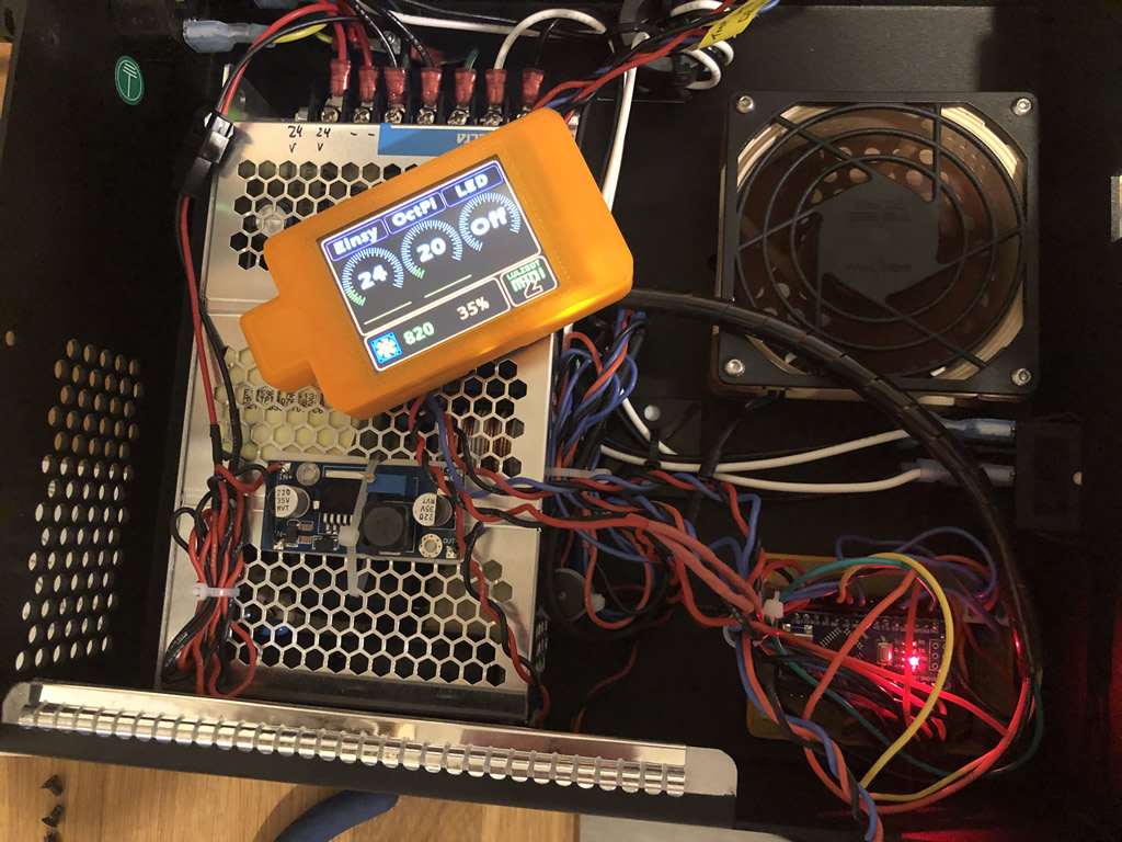


Comments: