
RTLapseCAM V2: Resin Printer Time-Lapse with TTGO T-Display & GoPro
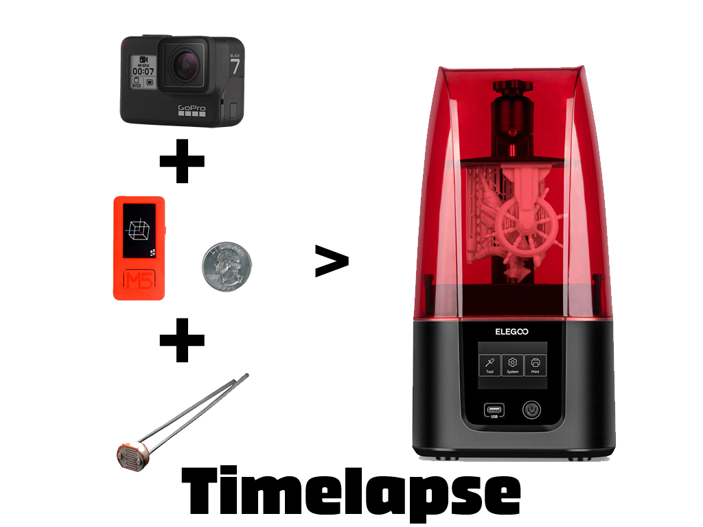
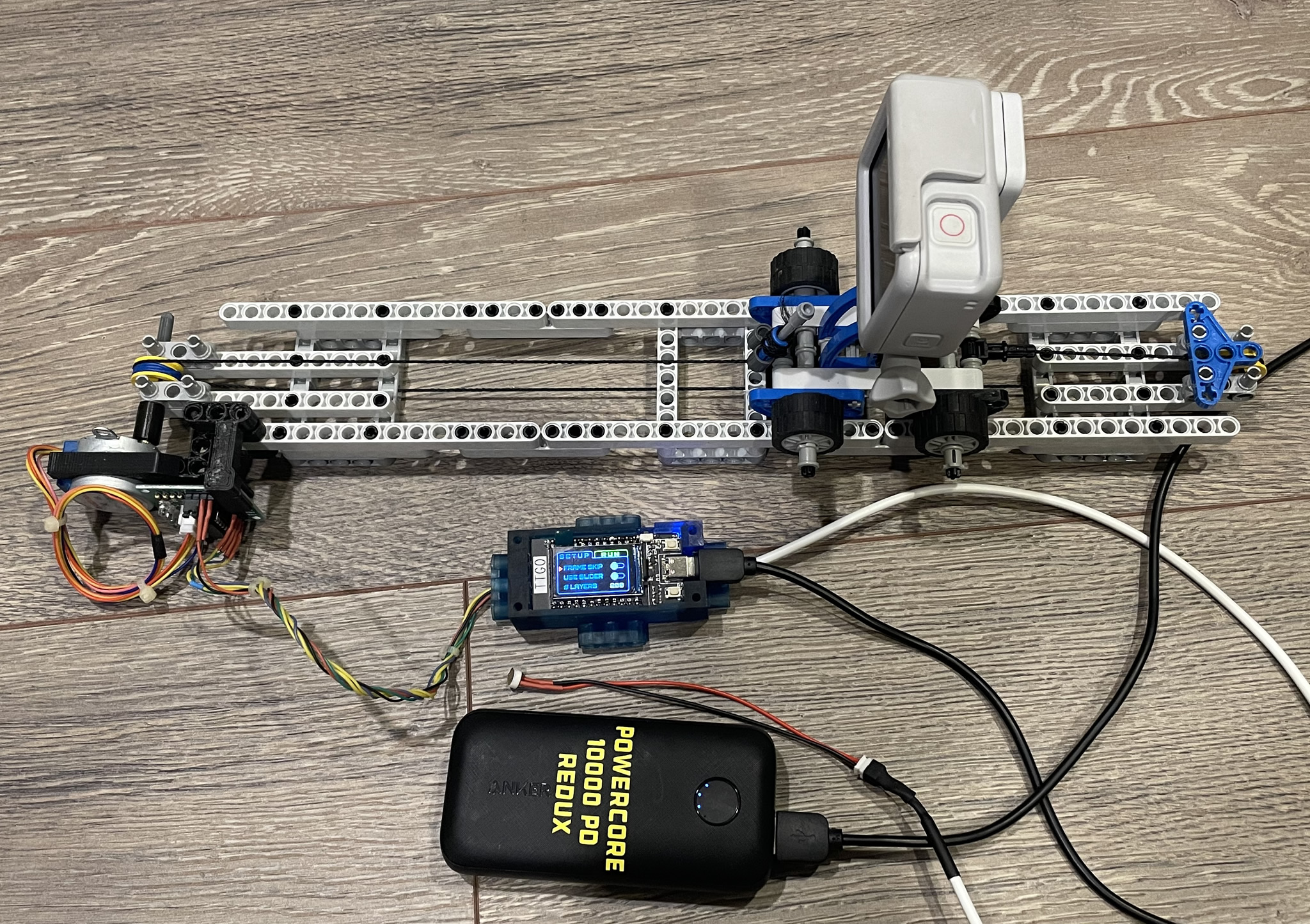
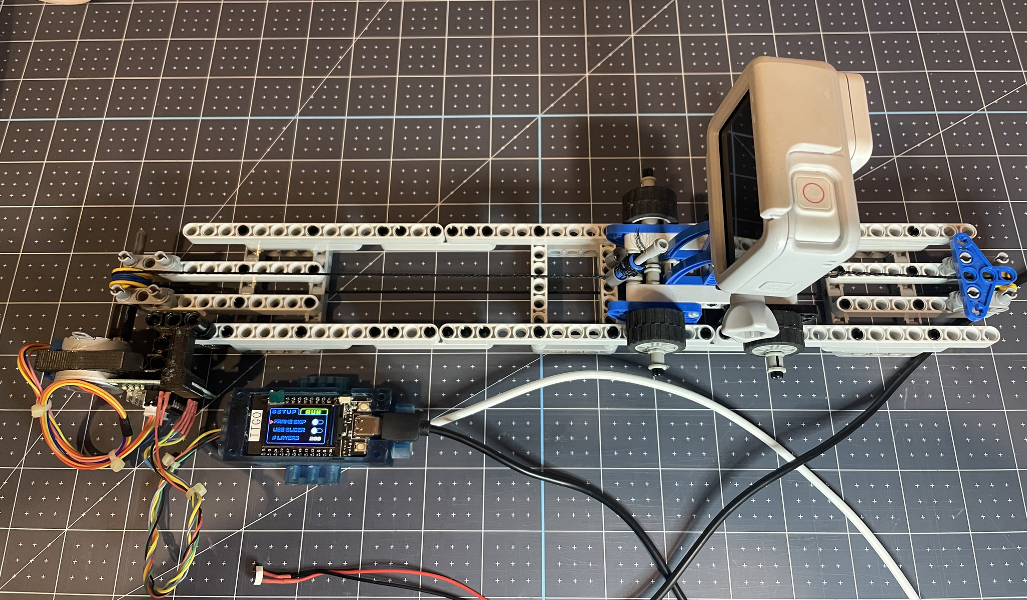
Not being able to leave well enough alone, I’m onto V2 of RTLapseCAM. A quick re-cap – the purpose was to take time-lapse photos of resin prints (using layer transitions) and stitch them together into a video. In the original setup, the GoPro sat stationary and RTLapseCAM triggered the photos. The result was ok, but it just showed the print rise out of the bed. I wanted to take it to the next level by having the camera draw back as the print rises out of the bed. I built a LEGO slider rail and truck, threw in a stepper motor/controller and a TTGO T-Display. The video sample below demonstrates the effect on a small print. Read on for build details and a walk-through of the HMI.
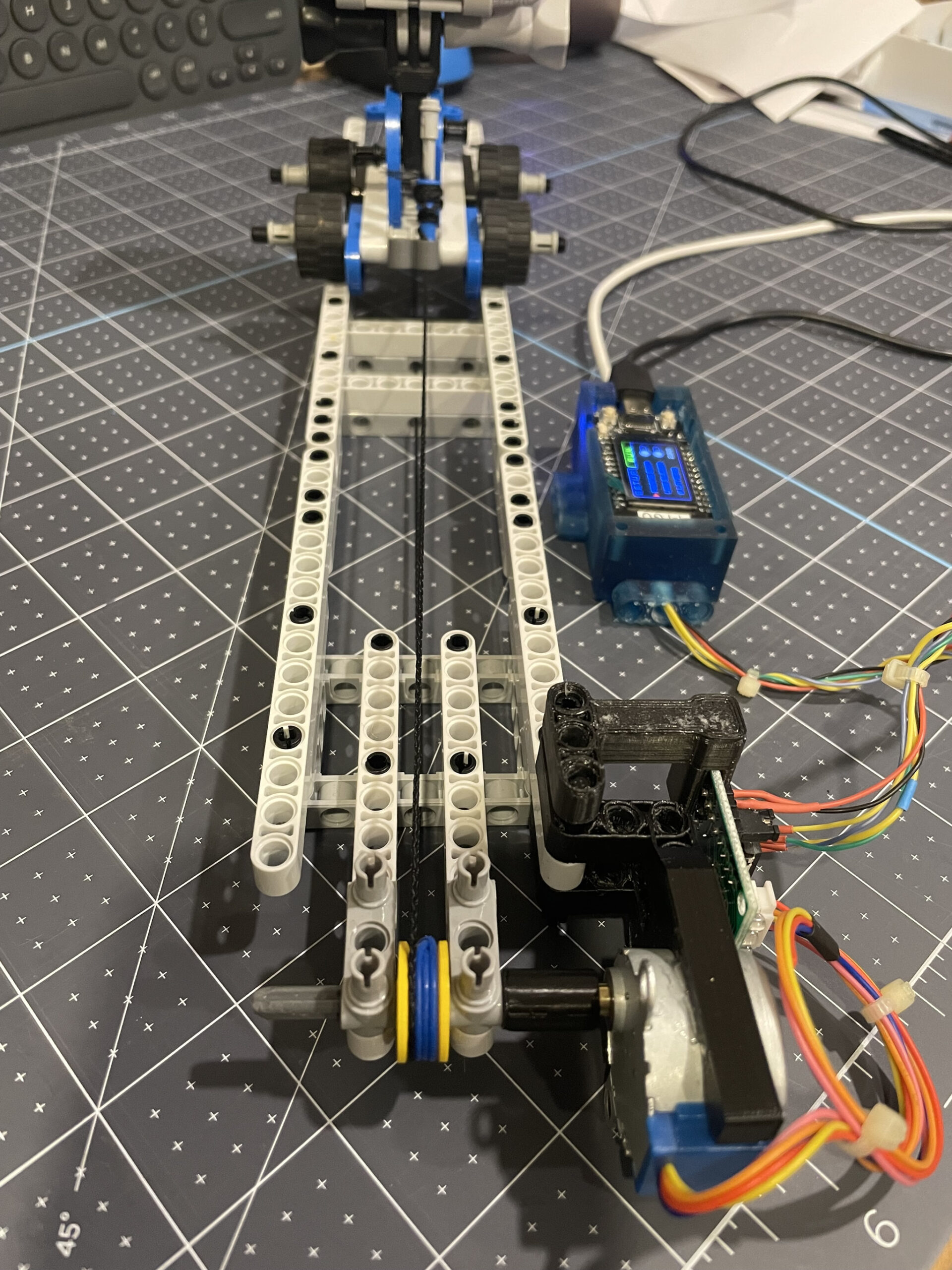
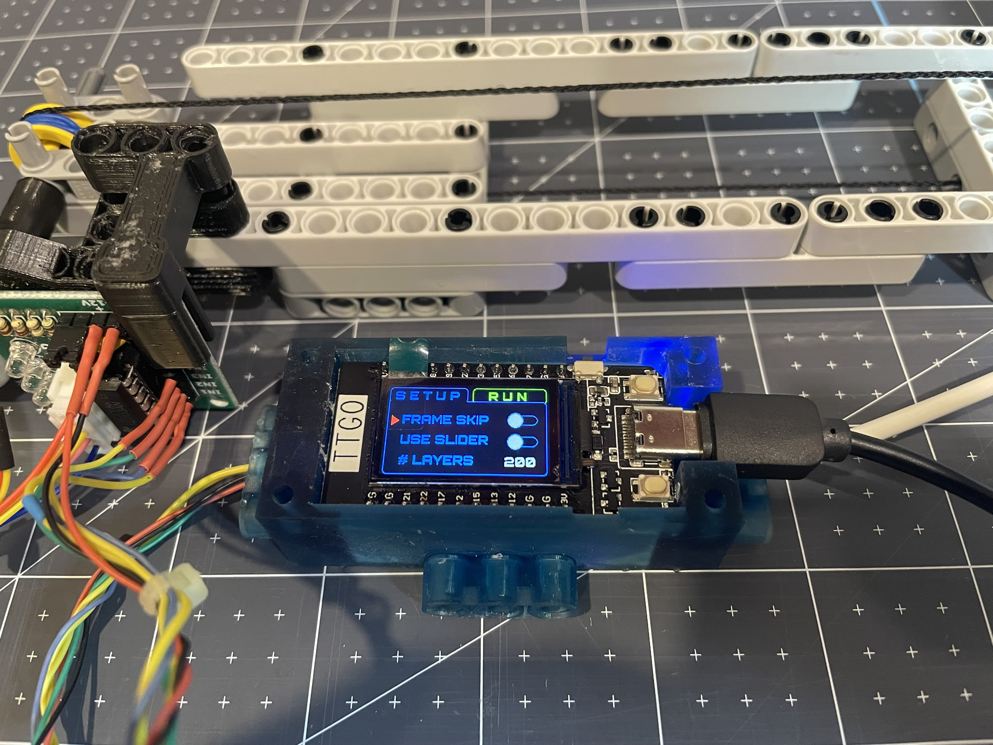
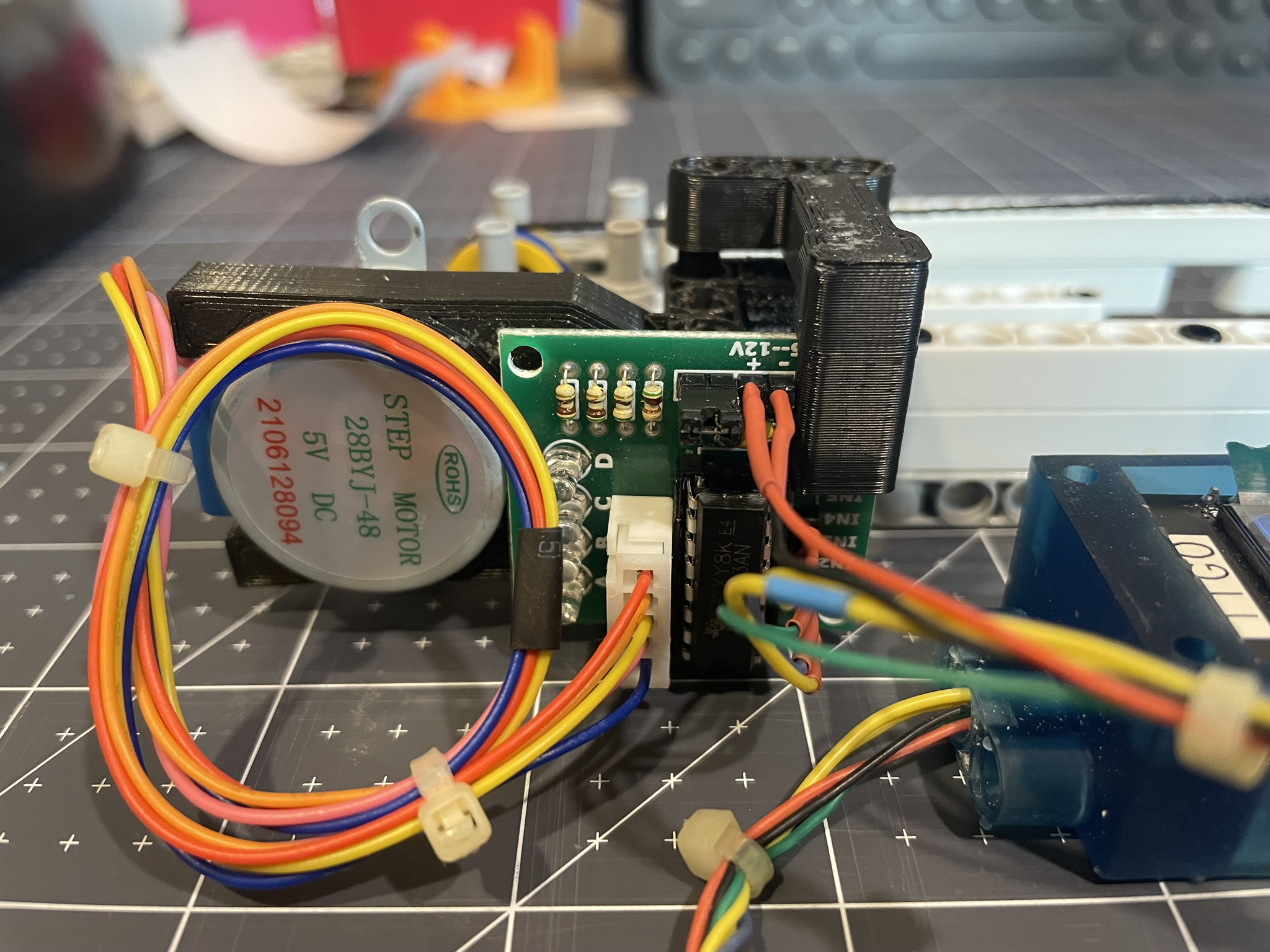
How it Works: The idea is to have the camera slide backward away from the printer over a period of time while capturing photos with each layer change. The rail size is fixed but prints can vary in size (# of layers) which poses a challenge. Knowing the stepper motor was the right solution, I didn’t have one but did have a N20 gear motor sitting around, so decided to throw it in there to try while I waited for the stepper. Since the motor is geared to approx 30RPM, very small pulses yields short movements of the camera truck. Using some simple math including # of layers it could change the pulse timing to move the slider a bit with each layer. The fewer the layers the longer the pulse the farther the slider moves. However, as suspected, it wasn’t very accurate and did not always use the full slider. The new iteration uses a 28BYJ-48 Stepper Motor with ULN2003 controller. The full rail distance amounts to 18100 steps in this setup. This constant along with being able to input the number of layers in the TTGO HMI + some simple math, the full rail can be used with each print. The result being it would always use the full rail length regardless of the size of the print. As I have yet to see a print that is greater than 18100 layers, I’m not worried about it. If it happens, it will simply stop…
The below video provides a walk-through of how the system works. Again, have a look at RTLapseCAM V1 to get more info / videos on how it works.
Components / Materials:
- Microcontroller: TTGO T-Display ESP32
- 28BYJ-48 Stepper Motor with ULN2003 driver (or a 5 pack)
- PhotoResistor
- If you are looking for a resin printer, check some out here
- You can check out RTLapseCAM V1 for other components used in this project
- Full disclosure, I get a small referral fee if you buy from the above links at Banggood.com. You don’t pay any more, but a fraction goes to me to help support my projects. Thanks for your support!
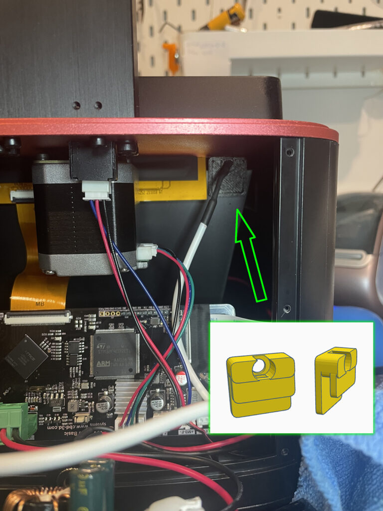
This shows the LDR (photoresistor) sensor installed using a custom printed bracket (you can download it here). No glue or screws were used. It just pressure-fits along the plastic rim looking over into where the UV LED’s shine up onto the TFT screen. It also does not interfere with the light path/screen etc. The area at the top there is open between the red metal top plate and the black “bucket” that holes the UV LED’s.
Your Support is Appreciated: A lot of time is put into designing and building these projects, the creation and editing of videos and pulling together my build logs. If you find this useful, please consider a small donation – buy me a coffee as they say 🙂 It will go to purchasing new items/components for future projects and help support the work I do here. You can support me either via Ko-Fi or Paypal below. Additionally, clicking the above product/part links also helps and it costs you nothing. Thanks!


Comments: