
DIY Quadcopter Build (MultiWii / NanoWii / Qbrain)
 If I didn’t have enough hobbies already… I’ve just gotten myself into the world of quadcopters and flying. I’ve never flown before. My RC experience is limited to 4 wheels on the ground. Navigating with 2 sticks and learning the world of yaw, elevation, pitch and throttle has become my next challenge. I’ve wanted to learn how to fly for some time, so here we go..
I’m not going to re-create the wheel as credit goes to the folks over at marginallyclever.com for putting together a great build log of the DIY Betamax Quadcopter. In a nutshell, for less than $300 you can build a very capable quad that should give you plenty of fun and also provide the ability to mount some small and light equipment. There’s also lots of optional add-ons like GPS that will make the quad smart and more easy to use. It also uses Arduino-compatible MultiWii which is software that runs on the NanoWii to allow you to control your quad (or other RC machines).
Quadcopter Parts List
| Part Description | Qty | Notes |
|---|---|---|
| 8045 Props | 8 | Get at least 8 sets of these - you will break them. Each set contains 1 CW & 1 CCW prop. |
| Male XT60 connectors (5pcs/bag) | 1 | (for the Qbrain power leads) |
| Brushless Outrunner 1100kv Motors | 4 | (suggest adding 1-2 spares as well) |
| MultiWii NanoWii ATmega32U4 Micro Flight Controller USB/GYRO/ACC or Crius MultiWii v2.5 Flight Controller | 1 | |
| 4 x 25A Brushless Quadcopter ESC 2-4S 3A SBEC | 1 | There are a number of 4-in-1 ESCs out there. Get one that is at least 20Amps per channel. |
| 11.1V 2200mAh 3s Lipo Battery For RC Transmitter | 1 | For use with the 9x transmitter. (much better than a batch of AA batteries). Just make sure it fits the battery compartment. |
| LiPo Balancer/Charger | 1 | Get a good quality LiPo balance charger. You dont want to screw around with chraging LiPo's |
| Lithium Polymer Charge Pack | 1 | This is a MUST if you have LiPo's and charge them. We all don't want to burn down our houses! |
| Transmitter | 1 | You'll need a transmitter of course. The FlySky is a very popular Asian knock-off that has many features of the more expensive transmitters. This is the same as the Turnigy 9x. I also recently updated mine with Er9x firmware - highly recommended. |
Tips:
- You’re going to want to mounted something to aid in hard landings to the bottom of the quad if you are a noob like me. I’ve bounced this thing off the ground too many time to count as I have been learning to fly. I started with a pool noodle cut into doughnuts ($1.99. Nuff said), and since moved to sections of PVC pipe (see further down).
- I suggest at least 2-3 sets of props. I’ve already trashed
1 prop and 1 is dinged(now 6). Remember you will need 2 props per direction. 2CW, 2 CCW. - Motors – I only bought 4 and have bent 1 shaft in the first 20 minutes of flying. I suggest getting 1 or 2 extra motors. (Edit – I have now had the quad for nearly 1 yr, and have replaced 6 shafts. Each time I crash I always have 2 good motors, swap them out, then after flying go and install new shafts to the bent ones.
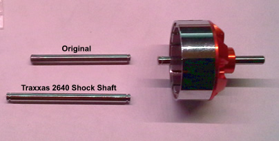
- If you end up going with the D2822/17 Brushless Outrunner 1100kv motors, I came across readily available Traxxas 2640 RC shock towers. Yep! They have the exact diameter (3.15mm) as the motor shafts, but are a bit longer (but are easily cut down). I’ve copied a pic below and can confirm that these fit just fine. The 2640’s are available at most hobby stores. I even found them at FutureShop (Canada)… This is a much cheaper alternative than replacing the motors. Update Dec 2014: I’ve had this quad for 8 months now and have bent a total of 5 shafts to date (and counting). Just did two today. These Traxxas shafts have saved me a lot of coin.
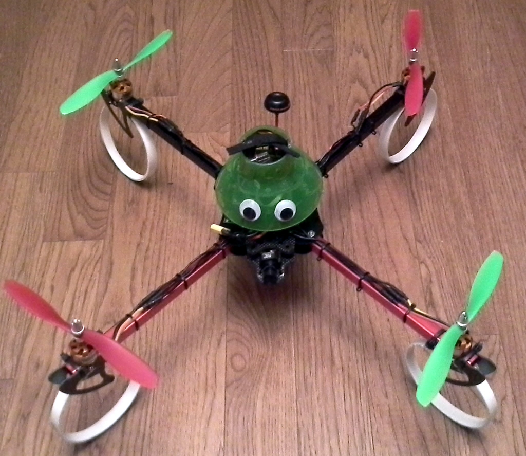
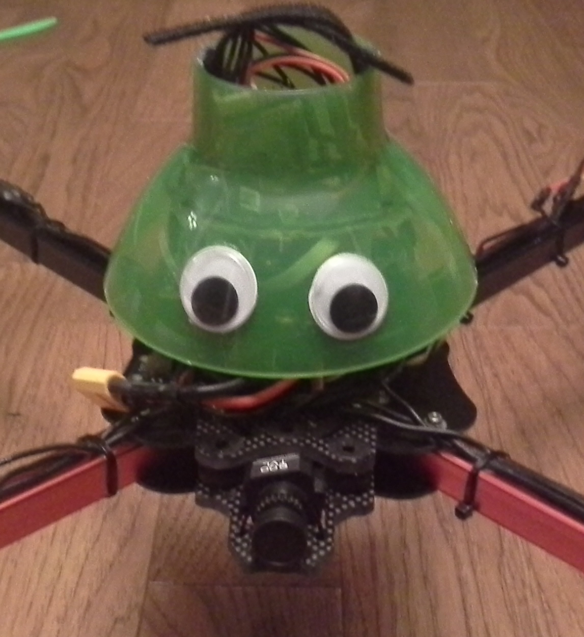
- You will want to cover the electronics with a dome. I have a makeshift top cover. If you look close enough you will see its from a Logitech mouse package and it works like a charm.
- Don’t finalize any gluing or irreversible securing of components until you have fully tested the unit. Use zip ties or quality tape to do it. In most cases, zip ties will do for good since you can just cut them if you need to move something.
- Fly in an open area clear from anything that bleeds! Yes. Those props are sharp and, with the speed they spin, you will loose a finger or gash yourself if the quad gets out of control. I did my first test flight in the basement with full winter jacket, hat and gloves on. ..and, flying in the basement is not the best approach either. Too restrictive.
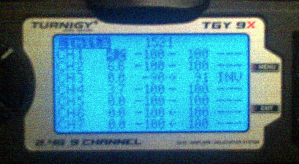
- Settings: When you get to setting the various stick ranges using MutiWiiConf.exe as described on the tutorial link above, if you are a noob like me, I suggest lowering the “Rate” value to something like 0.65 to start. You can see what I am talking about here. Look for the xy chart to the mid left that shows Rate 0.90 and Expo 0.65. Click in the green box beside Rate, drag your mouse until it lowers to 0.65. Don’t forget to click Write to write your settings back to the board. When I first started, the value was 0.90 and I could not stabilize the copter as the yaw and pitch are too sensitive for me. 0.65 makes it easier to control while I learn. I may even lower it a bit more until I get better. Of course, when you become an expert, you will want that value back up to 0.90 or more….
- Don’t forget that each time you download a modified sketch, you must re-rerun MultiWiiConf.exe and confirm settings / Calibrate the ACC.
- Arming your quad: You will likely read a number of other references that indicate to move the Yaw/Pitch stick to the bottom right / left. For my NanoWii, simply moving the Yaw (throttle) stick (left on Mode 1 transmitters) to the right and holding it there for a second or two did the trick. To disarm, move the stick to the left side and hold it there.
- Watch out when reading the manuals. I’ve already found 1 pinout error in the hobbyking manual for the NanoWii. See below under Bluetooth
- I’ve had my quad for about a year now and I’ve added lots of bits to it such as a lost model alarm, low battery alarm, FPV gear as well a some other custom bits. If you do this, make sure you always check to ensure the quad is balanced at the centerpoint. If it is not balanced, some of the motors have to work harder to keep the quad level – which will waste power and shorten flight times.
- Start with the following PID settings in MultiWiiConfig.
If you want to build your own, break out the credit card and simply follow the guide. I also suggest reviewing some of the approaches I have taken in the event you run into troubles. My build is nearly identical except I purchase an X550 frame. I’ve also created a parts list below of the items I purchased which are for the most part the same with a few exceptions.
Qbrain ESC Pins:
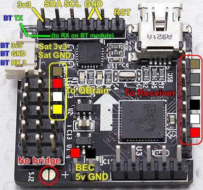
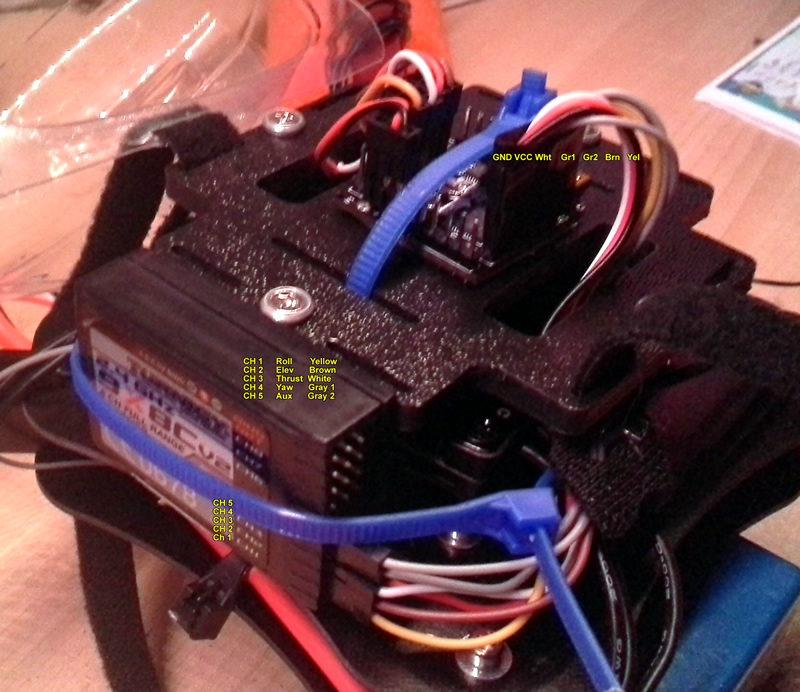
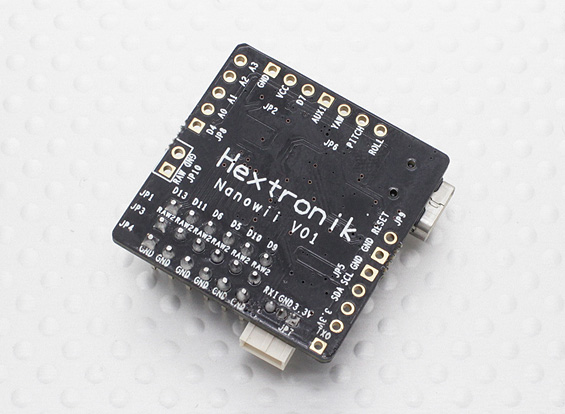
In my case, the below images show the wiring/pins between the NanoWii and QBrain ESC. There may be some differences in wiring colours. For reference purposes, my QBrain had the following assignments for each ESC: S1 Red, S2 Orange, S3 White, S4 Brown. The pins are shown connected on the left side of the below image.
[ad name=”GoogleAS728x90ImgOnly”]
Qbrain BEC power:
When following the Betamax Quadcopter build, and after doing some research, it appeared that the ideal way to power the NanoWii was by using the 3-Pin BEC and plugging it into the pinset shown to the left (3rd from the top where the white pin is shown). This would have as Black Red White for that row. To provide power using this approach, SJ2 was bridged with solder. However, this did not work for me. The BEC wire had 5V from the QBrain but nothing would work when I plugged it into the NanoWii. I finally gave up and pulled the 5V and GND from the BEC and put them to the power pins (shown at the bottom of the pic). IMPORTANT – if you do this, make sure you do NOT have SJ2 bridged or poof! Out comes the smoke!
Failsafe
One thing you need to ensure you have set-up and tested is the MultiWii Failsafe feature for you quad. As I am still learning the contents of the multiwii code, I am sure there are other settings in addition to those below (i.e GPS RTH) to enhance this feature. When I was researching this, I found many threads that suggested that the Turnigy 9x / FlySky transmitter does not have a failsafe feature – which I confirmed it doesn’t. However, the MultiWii code does and I confirmed today that it does work with the 9x.
Essentially, what the 9X does is when the transmitter is turned off, the receiver holds the last settings it had before power was lost (you can confirm this in the MultiWiiConf application by doing a test). Then, the MultiWii code detects power loss by not seeing the pulses from the TX. This triggers the failsafe code to kick in (shown below). What it will do is throttle down (see FAILSAFE_THROTTLE) to a value you set that will allow the quad to gracefully drop to the ground. In my case it is MINTHROTTLE (1100) + 250 = 1350. You can determine what you should change the value for this by doing some simple tests in the field. I found that having the throttle just below the mid stick level spins the motors at a speed that allows the quad to slowly come down. When looking at MultiWiiConf, this position shows about 1350 in the GUI. I changed the value to 250.
To get it working, I followed a few steps:
1) On the transmitter go to Settings > Fail Saf > then set THR F/S to 000%. I am not positive this is necessary, but found threads that suggested it needed to be done.
2) In config.h, uncomment the below settings to enable the failsafe feature:
#define FAILSAFE // uncomment to activate the failsafe function
#define FAILSAFE_DELAY 10 // Guard time for failsafe activation after signal lost. 1 step = 0.1sec – 1sec in example
#define FAILSAFE_OFF_DELAY 200 // Time for Landing before motors stop in 0.1sec. 1 step = 0.1sec – 20sec in example
#define FAILSAFE_THROTTLE (MINTHROTTLE + 250) // (*) Throttle level used for landing – may be relative to MINTHROTTLE – as in this case (you may need to play around with the 250 value)
#define FAILSAFE_DETECT_TRESHOLD 985
3) Testing the feature can be done a number of different ways. If you don’t want to loose a finger, or your quad, I suggest taking off the props, turning the transmitter and quad on (while on the floor), set the throttle to 75%, then turn off the transmitter. If you are using the above code, after about a second or so, you will notice the motors spin down to the level 1350 (in my case) would give you (about 45%). It will do this for 20 seconds (see FAILSAFE_OFF_DELAY) which allows the quad to make it to the ground. After the 20 seconds is up, it will turn the motors off. Give it a try and see if it works.
Connecting a Bluetooth / OLED Module:
Update: I’ve since added an I2C OLED display module which changed the Bluetooth pins I’ve identified below. If you are not using an OLED module, follow the steps below, else follow the OLED + BT steps.
Bluetooth Only:
If you want to change settings on the fly in your quad, this is the next step once you’ve figured out the basics. Connecting a Bluetooth module will allow you to remotely configure the quad from an Android or other device. Check out MultiWii EZ-GUI for a nice app that will do this for you. Before you get started, the PDF in the files for the NanoWii section that shows the pinouts for the Spektrum satellite ports is WRONG!!! (we need to use the RX in that connector for the Bluetooth). The RX is the right hand pin (the manual says it’s the middle). For folks trying to get bluetooth working, here is what I did (using MWC 2.2):
1) In MWC config.h make sure #define “SERIAL1_COM_SPEED 115200” is un-commented.
2) I’m using a HC-06 Bluetooth module (from DX), but they should all be the same. I changed the baud to 115200 (see this) for details on how to change it)
3) Connect the BT VCC to either the 3.3v pin (just above the TX pin) or the 5V BEC VCC pin (this depends on what your BT module needs). I’ve got it working on the 3.3v pin (even though it should be 5V)
4) Connect the BT RX to the NanoWii TX (bottom left pin)
5) Connect the BT TX to the NanoWii RX (right pin on Spektrum satelline 3 pin connector).
Voila it should work with your app. I’m using the Android MultiWii EZ-GUI
Bluetooth and OLED:
- Bluetooth Module: Looking at the Sat (3 pin connector – below top left) – Pin 1 goes to BT VCC, pin 2 goes to BT GND, pin 3 goes to BT TX. In the image below, the TX pin is marked with the BT TX (blue/green text) but it does not show the pin post soldered in. This is the TX pin and goes to BT RX.
- OLED Module: Looking at the 6 pins with posts (below pic – note the post for TX is not soldered in pic) at the top of the board: The first is 3v3, the next is SDA, the next is SCL and the next is GND. Connect these to the matching pins on the OLED. Note, to get the LCD working, you will have to un-comment LCD-related lines in your config.h file. See www.multiwii.com
Baro / Angle Mode using a 3-Position Switch – 9x Default Firmware
Note: Details on setting this up on er9x are below.
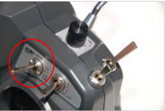
I was looking to switch between normal Acro mode, Angle Mode (stabilize) and Baro (Altitude Hold) from my Turnigy 9x. I wanted to use the Aux3 F. Mode (mix) 3 way toggle switch (see pic).
1. On your Turnigy 9x – Go to the AUX-CH menu and set CH6 to “PIT TRIM’ The Pitch Trim dial will be the “basis” for the mix. In my case, I left the trim dial at the lowest value (all the way counter clockwise).. below) to flip between the 3 modes. Given I’m still learning, there may be other ways to do this. After some research, here’s what I found that make it work.
| 2. Go to PROG-MIX menu and enter MIX 1, then enter the following settings:STATE ACT MASTER FLP SLAVE AUX (The first one – there are 2 AUX values to select from) OFFSET -100 UPRATE -100 DNRATE -100 SW NOR3. Go in to MIX 2 and enter the following settings: STATE ACT MASTER FLP SLAVE AUX (the second AUX) OFFSET 000 UPRATE 100 DNRATE 100 SW ID24. Go into MIX 3 and enter the following settings:STATE ACT MASTER FLP SLAVE AUX (the first AUX) OFFSET 100 UPRATE 100 DNRATE 100 SW ID2(note, the link above indicated that only 2 mixes were necessary. However, I had to add the 3rd mix in order to get the 3rd position to work.For the values to register on the Quad, you have to enable Baro in MultiWii. I also have the 9x receiver channel 7 running to the Aux1 pin on the NanoWii. The following shows the 3 modes registering in MultiWii Config (Android version) |
 |
Baro / Angle Mode using a 3-Position Switch – er9x Firmware
Jan 2015 – Hearing all sorts of good things about er9x, I figured what better way to have fun on a cold Sunday in January. The process for setting up mixing is similar to above, but not as complex (and makes more sense AFAIC)… Similar to above, I have Ch7 on the RX going to Aux1 on the Nanowii. The difference in this case is that it did not require using the Pitch Trim Aux channel. As a result only 1 channel gets tied up here. The purpose is to allow Aux 2 (3 position switch on the Turnigy 9x) to switch between flight modes. I also recently added a Mag sensor (compass) as I am still a noob at flying and need all the help I can get. …and of course, I like to muck around and figure things out. I was aiming for 3 modes here.
First step is to set-up the Transmitter. In er9x, go to the Mixer settings.
- Scroll down to CH7 and create a new mix. Modify as follows.
- Source = FULL
- Weight = 0
- Switch = ID 0
- Exit the mix for CH7 (Exit Button).
- Scroll down to CH7. Press “MENU” once, select “INSERT”create a new sub-mix. Use the following settings:
- Source = FULL
- Weight = 50
- Switch = ID1
- Exit the mix for CH7 submix 1 (Exit Button).
- Again, scroll down to CH7. Highlight submix 1 and press “MENU” once, select “INSERT” create another sub-mix. (this will be a second mix under Ch7). Use the following setttings:
- Source = FULL
- Weight = 100
- Offset = 55
- Switch = ID2
- Once complete, programming the Tx is done.
| The next step is to test the settings. On the Tx, go to “MENU”, then select “Radio Setup”, scroll to “DiagSwtch”. Look for ID1 and ID2. With the toggle switch set to “N”, both will show “0’s”. Toggling the switch to “1” (middle position) should show ID1 = 1. Toggling the switch to “2” (bottom position) should show ID1 = 0 and ID2 = 1. You can also see this on the home screen when you scroll to the graphical display – it will show the bar being full left, none, then full right. Example of what it should look like when done (sorry for the bad pic). | 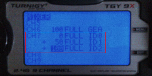 |
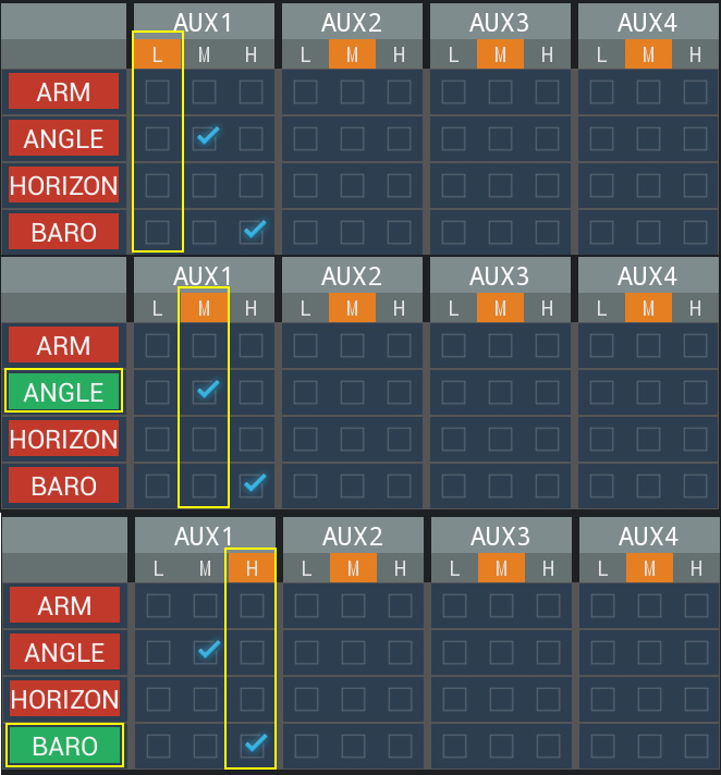
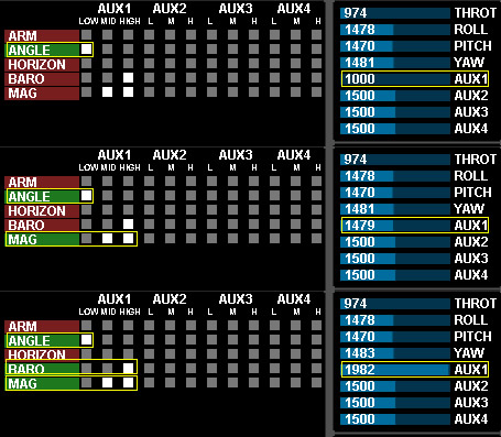
Now plug your computer into your quad and start MultiWiiConf. Turn on your Tx. When you toggle the switch through the 3 positions, you should see Aux 1 going from a low value ~9xx to a medium value ~1500 and a high value ~1900. The numbers are not as important is seeing the graphical bar grow from left to right. If you do not see this, it is likely because you have got the wrong wire connected to the receiver (make sure it’s connected to Ch7).
Once this is confirmed, you can now set which features are to be enabled with each toggle. One thing that confused me is that I expected to see each of the “L”, “M” and “H” columns highlight in the Aux 1 section of MultiWiiConfi highlight when I toggled the switch. However, you have to first tell it what you want it to do. For each mode, move the mouse into the box and check it. For each one, make sure to click the “Write” button to commit the changes to the controller. Each time, also click “Read” to ensure the box is still checked. Go through each toggle N, 1 and 2 and set the modes. Once done, you should see the Mode components highlight green as you toggle the switch. The boxes should remain checked for the settings you set.
For my setup, I configured as follows:
Tx Switch at “N” (home position) – Angle mode (I need all the help I can get !)
Tx Switch at “1” (middle position) – Mag and Angle Mode – allows the quad to auto-level itself as well as keep Yaw heading the same way ( essentially I don’t want the ‘front’ of the quad rotating due to drift”.
Tx Switch at “2” (bottom position) Mag + Anagle + Baro Mode – all the above + hover at the height it was when toggled to this mode.
Trimming Inputs (ER9x):
Having recently updated my TX firmware, I had to set the trims for the 4 main channels (Thr, Ail, Rud, Elev). This is more of a reminder for myself and for posterity sakes. To get my quad trims aligned for all 4 channels in MultiWii, I had to first go into Mixer and ensure all channels were set to 120%. See pic below.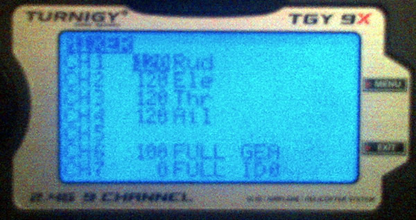 Pretty self explanatory on how to do this on the screen. Then, clicking the Limits, I had modify the subtrim for each channel to get the mid-stick levels as close to 1500 as possible in MultiWii Gui (see pic above for examples – which are not trimmed – eg 1470). Sorry for the lame picture quality. To adjust each sub-trim, have the quad connected to MultiWii Gui, and navigate to CH1’s subtrim, click Menu, then the Up/Dn key to modify (by 0.1 increments) while watching value/bars in MultiWii Gui. Get the value as close to 1500 as possible. Hit Menu to save. Do the same for the rest of the channels. For the Throttle, you will have to center the stick first. In my case, I also had to adjust the endpoints of the Throttle as I was having issues not being able to arm the quad (the original low value was < 1000). I got it up to about 1015 or so.
Lost Model Alarm:
It’s always a good idea to have a lost model alarm in the event that your quad goes down in the bush or off into the distance. You can buy one, or DIY your own. As usual, I went the DIY route and built my own using an ATTiny to provide some enhanced functionality – check it out.
Landing Gear:
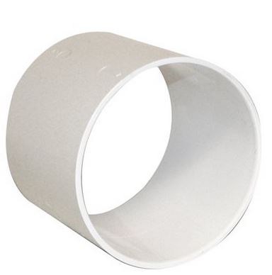
As a first time flyer, I was certain there would be a lot of crashes, so I wanted to protect this thing during hard landings. I started with cutting segments of a pool noodle and then using zipties to secure them to the ends of each leg. These work great BTW, but they also wear out fast. In my search for another solution, I came across a sewer coupling while browsing the new Lowes in our area – cant complain for $4 CAD. There are lots of similar products out there, but many of them are too thick (walled) and won’t have the bounce necessary to add spring to a hard landing. This one has a wall thickness of ~3mm – which turned out to be ideal. After cutting the pipe into 4 sections approx. 15mm wide, I had a full set of landing gear. There’s also enough pipe left to make a second set as well. You can see these units mounted in the pic at the beginning. They work well and, if anything, are a bit bouncy. I’m going to add some chair leg end stops (the cloth-like sticky ones) to help soften the bounce. Also, the PVC has a lot of flex to it and does not warp unless a lot of force is applied. However, this is what I want in case of a really bad fall.
Receiver Pins:
The receiver pins are connected as shown on the right side. In my case, mine had 2 gray pins (nice!). However, its pretty easy as they are simply in the same order of sequence between the TX and NanoWii (see 2nd image below)
Note the BEC standard 3 pin 5V|GND|Signal cable did not work. Moved 5V and GND to 2 power pins at bottom.


Comments: