
LulzBot Mini: Arduino Temp Monitor / Fan & LED Controller
 I’m on a mission to reduce the amount of noise my LulzBot Mini 3D printer makes.
I’ve already added a motor damper to the Y axis. However, one thing that is consistently noisy is the case fan. It’s on at > 70% nearly all the time. In addition to this, the air vent fins in the side of the case amplifies the fan noise. So, I decided to build my own fan controller. Killing 2 birds with one stone, I also wanted to merge my LED light controller into this project.
What does it do?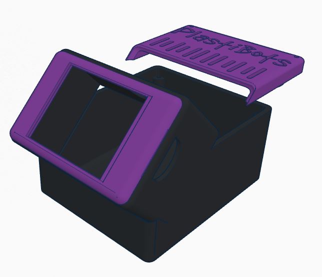
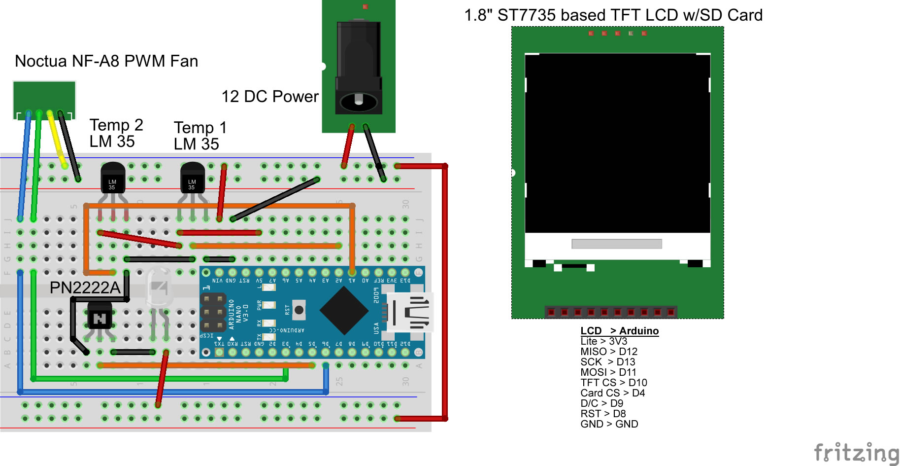
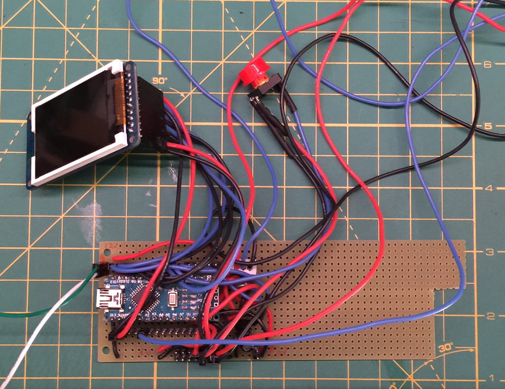
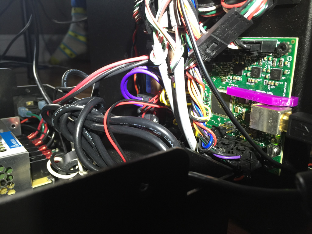
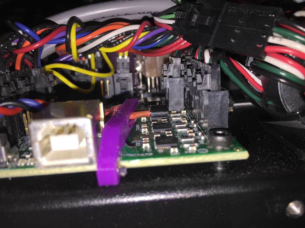
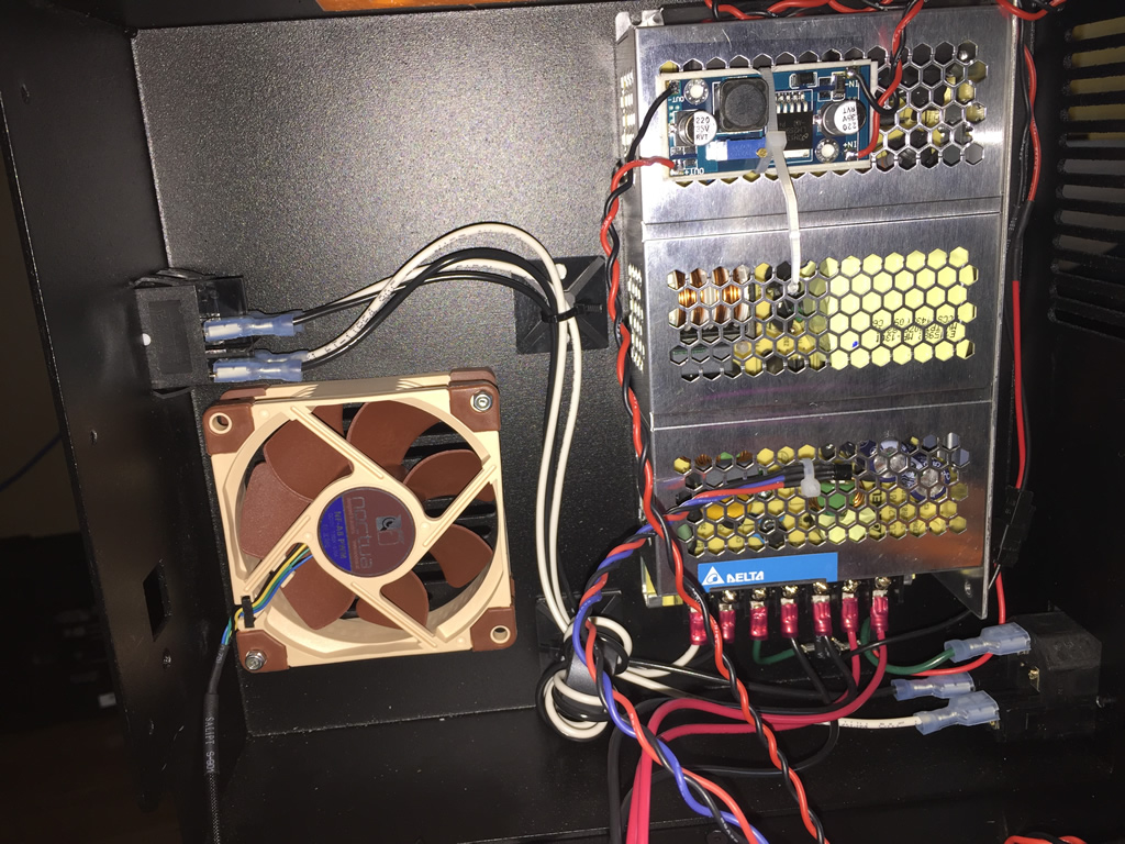
Pretty straight forward. An Arduino Nano is at the heart of it. It monitors 2 temperature sensors mounted in areas that get hot. Before selecting the locations, I ran a test print and used my laser temperature gun on the main board to see what areas got hot. As expected, the 4 motor driver chips on the RAMBO boards were it. They ranged from 30 C (idle) to 85C (printing). As the X & Y axis get the most action, I mounted a sensor directly to one of those chips. The other was mounted to the power supply, but this does not get very warm. When the printer is turned on, the Arduino controller idles the fan at about 650 RPM. It never turns off. At this level, you can’t even tell it’s on. When printing starts, the Arduino polls the sensors every second and adjusts the fan speed based on the stepper motor controller chip temperature. The sensor returns Celcius values. Temp ranges (30-90C) are mapped to the AnalogWrite function to control the fan speed from idle (~650RPM) to full (~2200 RPM).
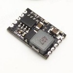
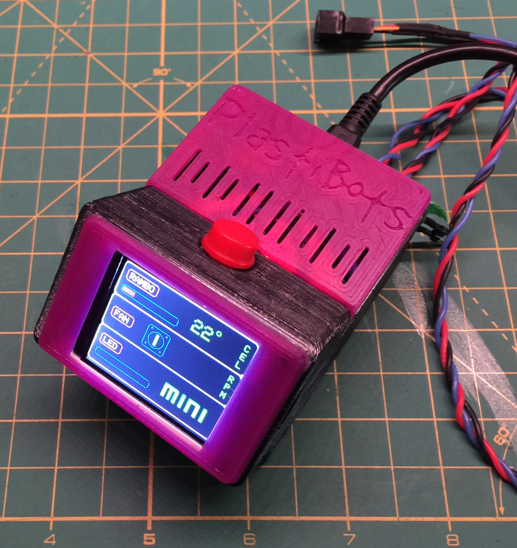
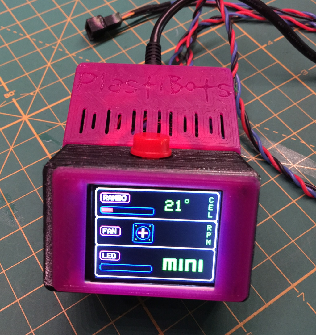
I also merged LED control into this project. It has a push-button on top. Using an interrupt, it allows switching between high, medium and low light levels. The display is there for s*its and giggles really.. I had some laying around and thought it would be cool to provide some visuals. That way I would have something else to do for those times when I find myself staring at a print job for prolonged periods of time. The display shows the RAMBO and power supply “SUPL” temps, the LED level, an animated fan icon, the fan RPM and voltage being applied to the fan. The Mini stock fans are 24V, but for this project I dropped everything to 12V.. The project, LEDs and fan are all powered by a switching regulator that takes 24V from the internal power supply and drops it to 12V.
It’s also important to note that this project is not specific to any one device. It is completely standalone. Simply supply 12V and mount/glue the temperature sensors wherever necessary.

How well does it work?
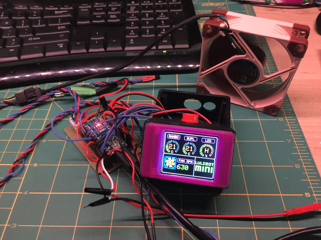 I’ve mounted the temperature sensors, the fan, connected power and have started further testing. Overall, I’m very happy with the result. The fan is quiet now and idles at about 600 RPM. Once the printer starts and the driver chips begin heating up, it ramps up to 1200 RPM. Even at this speed the fan is barely noticeable. The hum of the steppers stands out more now. Before I mounted the temp sensor, I used by laser temperature gun to monitor the status of the motor driver chips both during idle as well as printing. Given the X & Y motors do a lot more work, I focused on those 2 chips. At idle, they hovered around 30-40C. During printing they would heat up between 65-80C. With the case closed, I don’t think they would normally hit 80C. This happened because I was mucking around in the case and the stock fan was not able to do its job (too far away with the case open).
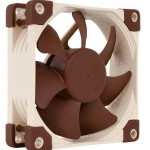
When I mounted the LM35 directly to the chip, the readings were much lower (high 40’s during printing). There could be a number of reasons for this. The Noctua could be doing a good job, or there is some loss in thermal conductivity with the glue I used to mount the sensor to the chip (did not use thermal past). However, there is only a very thin layer of glue between the two. At the moment I’m mitigating this by dropping the maxTemp value so the fan ramps up more quickly. I’ve got some tiny heatsinks on order. Once installed, I’ll mount the LM35 to the sink itself and calibrate the temperatures after further testing.
Update: March 10th:
So, I’ve been printing now for a week or so and have a few observations:
- The fan control approach is working well. However, it does go through a dynamic process (uses the Map function). I don’t think this is necessary and may change the approach to a stepped one. i.e. temps from 20-30C low speed, 30-60 med, etc.
- The power supply temperature monitor is (as suspected) pretty useless. However, what I did come to realize is that I should be also monitoring the area of the RAMBO board that heats the extruder. At start-up, the mosfet gets pretty warm but the fan is still on low. I’m going to move the 2nd temp sensor and have logic to allow both temperature sensors control the fan. As an example, if the extruder mosfet temp is hitting 40+ C but the X axis is still idle, it will still kick the fan in at medium speed.
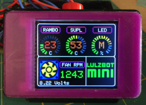
Interface Layout:
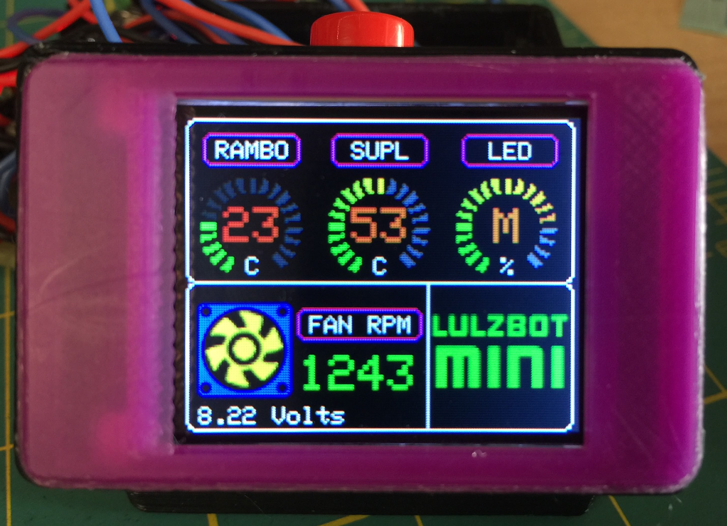 The screen displays key information including current temperature of the case (both a bar and numeric). The fan icon will show when the fan is on / off (based on animation of the icon, as well as a number in RPM’s (currently not shown). That number dynamically updates every second. The bottom shows the current LED level – an empty bar is off, then it shows % levels based on the switch being toggled. The screen displays key information including current temperature of the case (both a bar and numeric). The fan icon will show when the fan is on / off (based on animation of the icon, as well as a number in RPM’s (currently not shown). That number dynamically updates every second. The bottom shows the current LED level – an empty bar is off, then it shows % levels based on the switch being toggled. |
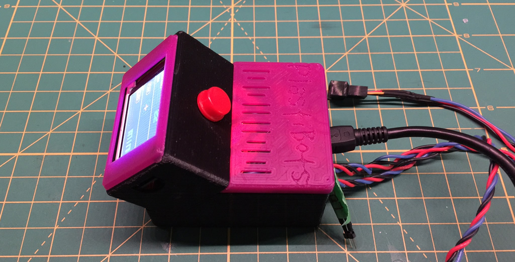
In Action:
Scalability:
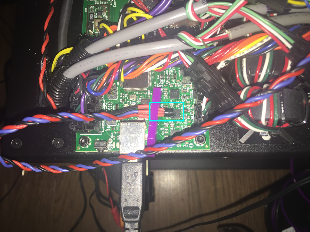
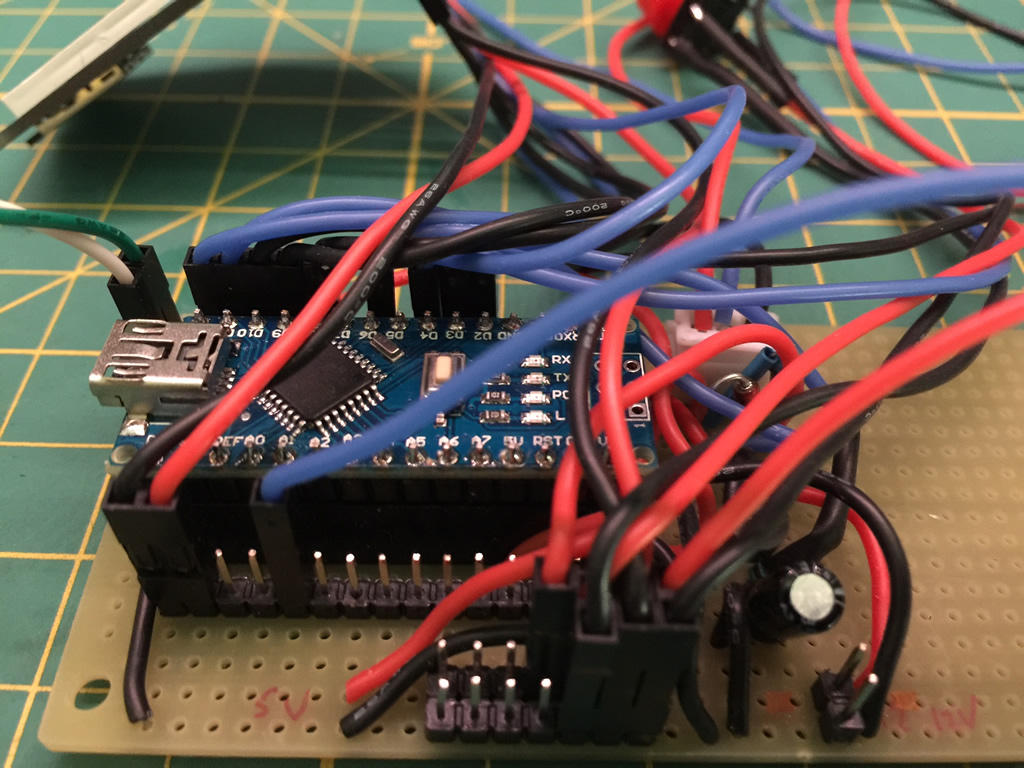
 I went with a different approach for this project. I have enough projects under my belt for some lessons learned. A common theme I find is that I want to change things up days or weeks following the completion of any given project. The issue is that when you solder components directly, you run into a mess trying to shuffle or add things. So, I went with a more modular approach:
- Used headers for the Nano. This allows me to swap the unit in/out. I’ve been doing this for the last few projects. It also makes it easy to pull the micro controller out for other projects.
- Headers for all Arduino pins to support future expansion. This has already proven itself in this project as I’ve made numerous pin swaps while working out issues around interrupts etc.
- Sensors / motor control – Use a combination of JST or Molex connectors. This applies to the temperature, fan, and piezo connectors.
- In the future, I may “IoT”-enable this device, so having this flexibility is important.
- The project itself completely modular in that it does not have any direct ties to the LulzBot itself. The temperature sensors, LED could serve for any project you have. For this I sourced the power from the power supply (via a switching buck converter). You just want to ensure that it has approx 2-3 Amps depending on the LEDs and fan you want to use.
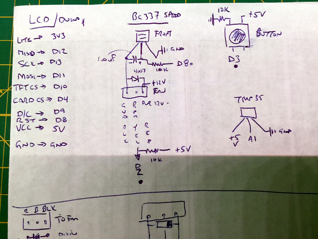
Connections:
Parts List / BOM:
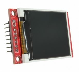
| 1.8″ TFT LCD | 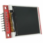 |
Breadboard | 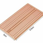 |
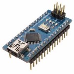
| Arduino Nano 328P
(5 pack) |
 |
Power Supply
(up to 3A) |
 |
| Silicone Wire
(20-24 g) |
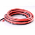 |
Noctua NF-A8- PWM (product link)
DC 12V Fan 4 pin |
 |
| Dupont Connector – 4 Pin | 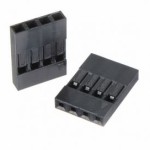 |
Dupont Connector – pin | 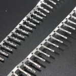 |
| Dupong Connector – 3 Pin | 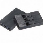 |
Dupont Connector – 1 Pin | 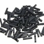 |
| Buzzer | 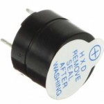 |
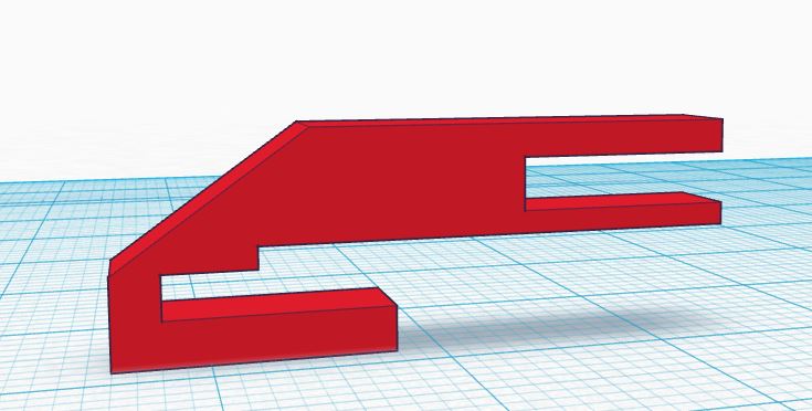
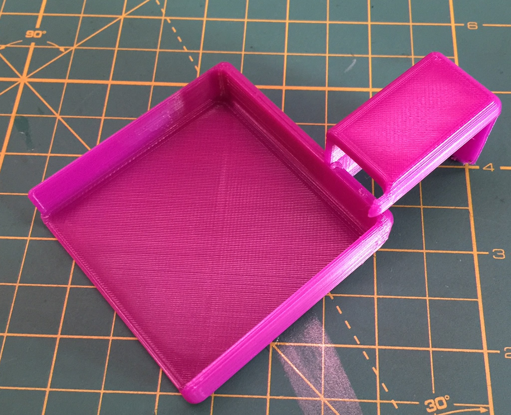
The Case STL files will be uploaded shortly | 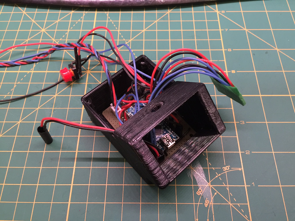 |
| Dupont Connector (general search) | STL files for case | 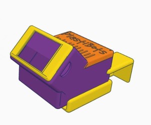 |
Source Code:
Although this was built to run on an Arduino Nano, it can easily be adapted to most other duino’s. However, there were few digital pins left after connecting the TFT, so I would stay with a Mini or higher. You will need the following libraries:
- Adafruit_GFX – graphics libraries.
- Adafruit_ST7735 – driver for the TFT. (Note I slightly modified mine to add a few colours (i.e. Orange). If you download this source and don’t want to modify the library, just change the colours to an existing one for each that throws a compiler error. Adding new colours is also very easy.)
- Just add: #define ST7735_DARKGRAY 0x7BEF and #define ST7735_ORANGE 0xFBE0 to the colour definitions section in Adafruit_ST7735.h.
- SPI – hardware interface to the TFT
- SD – if you are using the SD card on the TFT to render graphics. The 2 graphics used in this code have been included below.
Build Pictures:
|
|
|
|
|
|
|
|
|
|
|
|
|
|
|
|
|
|
 |
|
|
|
|


Nice project, a couple of questions:
The original fan on the mini is .55″ thich and the Noctua is 1″, did you have issues with this?
Are you still using interrupts for the speed control?
Will you please, please post the stl files for the case?
Thanks for sharing the info about this project.
Thanks for the comment. Answers: Yes, the Noctua is thicker, I just uses longer screws that I had laying around. I could not use the rubber (whatever you call them) screws that came with them. There is plenty of room inside the case, so the fan did not interfere with anything else. As for interrupts, yes. If you download and look at the code, I am using them for the LED and the speed control. As for STL’s, have a look again. I uploaded the files to Thingiverse and have linked them in the Parts/BOM section. If you end up building one, ping me if you post about it.
I finally received all the parts to start building the controller. While compiling, I get a message like “Sketch uses 31,840 bytes (103%) of program storage space. Maximum is 30,720 bytes.”, any suggestions?
Also, where do I find instructions to define the colors that create compiling errors(ORANGE, DARKGREY)?
Thanks,
cb
Hi cb,
Hmm.. I recall this compiling very close to 100% use on my Nano. Sounds like your Nano has a heavier bootloader that is eating up additional space. You may have to cut some ‘fat’ from the sketch to make it work. You could try commenting the section related to animating the fan. Or looking for some float variable items as they can be heavy. All serial prints should be commented out. If they aren’t, do that as they eat up space as well. Hope that helps. Should not bbe hard to get back 3%.
Colours: I updated the posting to include details for this. Just add: #define ST7735_DARKGRAY 0x7BEF and #define ST7735_ORANGE 0xFBE0 to the colour definitions section in Adafruit_ST7735.h.
Thanks Dave,
So onto the next hurdles, I can edit the define for the orange and the darkgray colors but I get a message indicating: ‘ST7735_DARKGRAY’ was not declared in this scope.
This is a snippet what the edited file looks like:
#define ST7735_YELLOW 0xFFE0
#define ST7735_WHITE 0xFFFF
#define ST7735_DARKGREY 0x7BEF
#define ST7735_ORANGE 0xFBE0
Regarding the “sketch too big” error message: I have the same nano board from the supplier you specified, I can only assume that the bootloader has to be the same….
The error is generated when I try to compile the code even without the nano connected at all, which indicates that the file is plainly too large to fit on the nano, are you sure that the posted code is the one you are running?
Do you use the SD card at all?, maybe deleting the associated code would be a good way to make some space.
I burned the official Arduino bootloader using a programmer but I get the same message.
Thanks for your prompt responses,
cb
OK, as soon as I posted the comment I realized that DARKGREY is not the same as DARKGRAY, sorry…
Still have size issue, though….
cb
Also, in looking at the code, where is the nano going to find the Lulzbot2.bmp file?, I haven’t downloaded…
Maybe that is the answer about the use of the SD card?
cb
That’s correct. Look at the back of the TFT LCD. There’s a SD card there. You have to load a BMP file onto the card which is then loaded in code.
Yes, I was aware of that, my thought was to delete the sd card related code to make room if the storage of the logo is the only function, small price to pay to make the whole thing work…..
Yup.. Getting rid of the code that loads from the SD card would reduce a lot of fat. The whole BMPDraw function could be deleted and related SD card code. That should free a lot of space up.