
ESP8266 Window Sensor with OTA and Deep Sleep
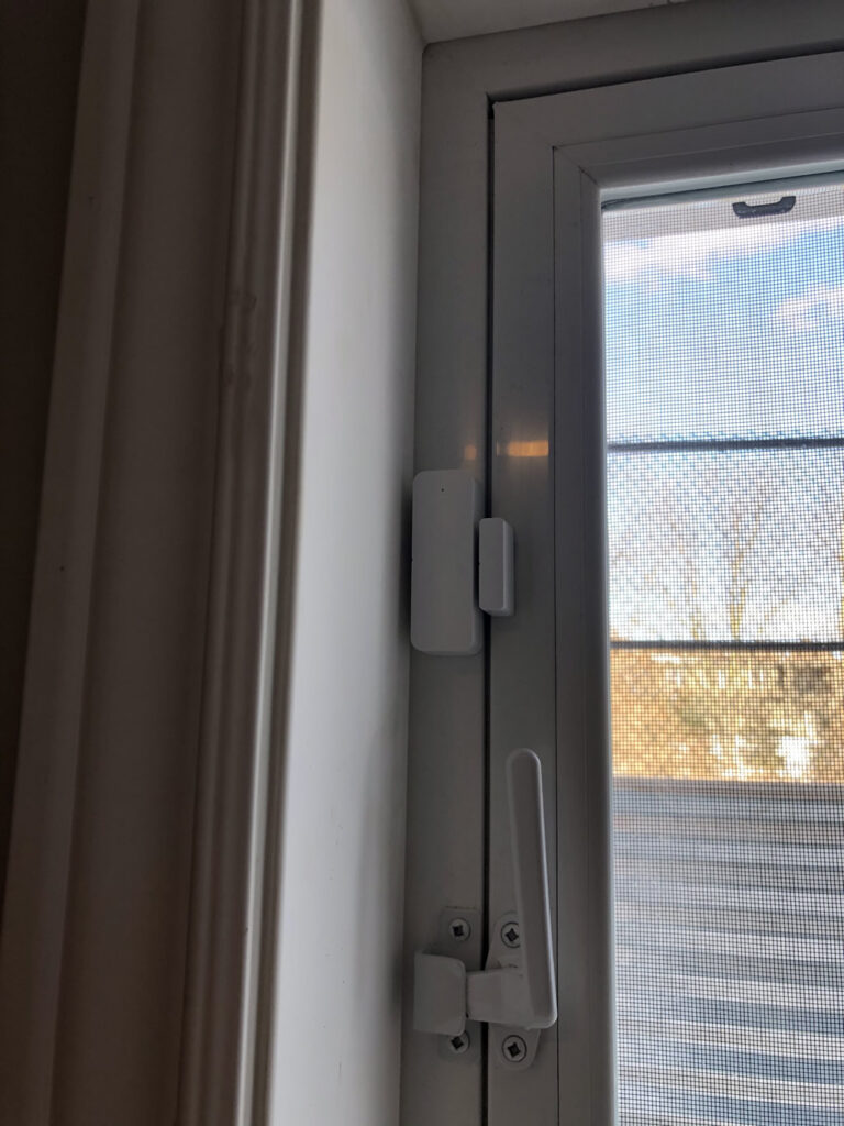
I was looking to boost my home security by adding window sensors. Something small and obscure so it would not stand out. I landed on this axGear sensor unit. It is small (70 mm x 20 mm). However, there was only one problem – it comes with proprietary software that I’m not sure I can trust. I also intended to integrate it with the ecosystem of devices I’ve created which I manage using Blynk. Of course I knew this going in and fully expected to hack it apart to make something that would work and probably break things in the process.

Most of these devices are based on a simple principle. They comprise of a simple circuit that uses a reed switch (or similar) that is triggered by a separate magnetic unit when a window is opened. In this case – and this is key to the idea of ultra low power – the reed switch is “normally closed” meaning when there is no magnet nearby the reed switch closes and powers up the unit which then triggers an alert. When the window is closed, the magnet holds the reed switch open, and no power is provided. This is why batteries last so long in these things. In this case, the unit would last as long as the batteries could sitting idle – likely many years. Now of course we all know that’s not quite true as this window will be open at times to let fresh air in etc…
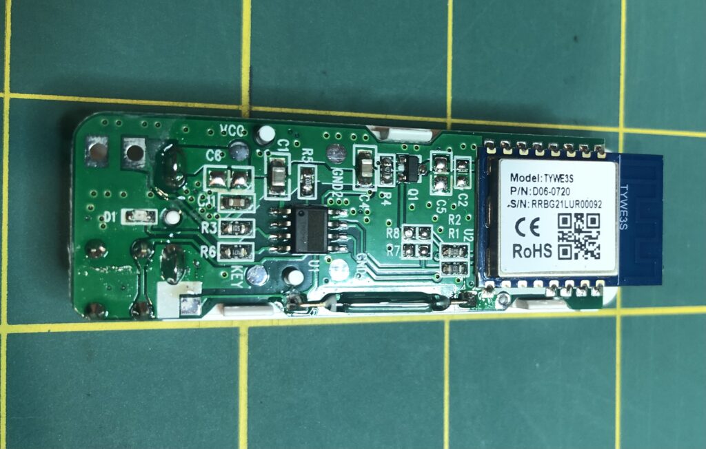
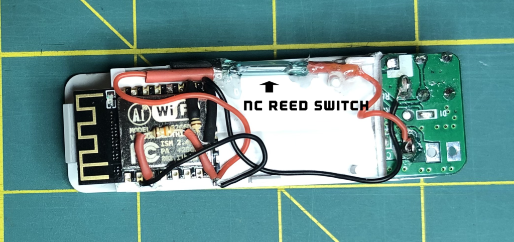
Here’s the innards of the stock unit. Key components are an ESP8266 (TYWE3S branded), the reed switch, a reset button (other side), some caps and resistors. There was also an 8-pin IC that conveniently had the main part # ground off (hmm?). I suspect it’s job was to trigger certain power states, led status and the reset feature. The TYWE3S pinouts are similar to the ESP12 module.
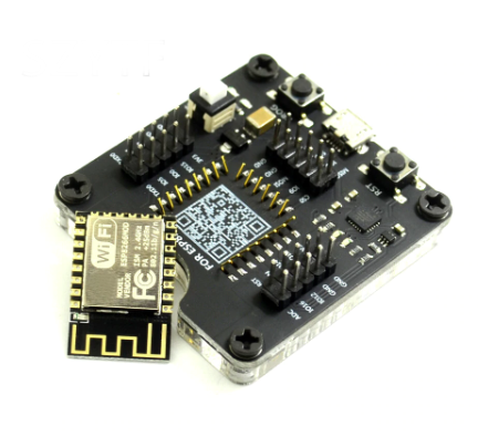
My original intent was to use the circuit above and bypass some parts of it. However, after unsuccessful attempts at trying to program the ESP on-board, I gave up and decided to remove it and instead used my ESP programmer. I also didn’t need all the extra circuitry as my design was much more simple. I’m kicking myself a little here as I have dabbled in the ESP world for years and always went to the pre-built units (e.g. NodeMCU) as it seemed too difficult to program these suckers alone. Now that I have an ESP Programmer, I have a path forward for future projects.
Poking around the main circuit board, I couldn’t figure out what it all does and didn’t need the stuff anyway. The goal was to use a very simple circuit with power directly to the ESP with the reed switch in between. It would be powered down until the window opens. When this happens, the magnet is removed, closing the reed switch which powers up the ESP allowing it to send a notification to my phone via Blynk. It then waits for 60 seconds (can be extended via Blynk) for OTA if I want to update the code, then goes to deep sleep (while the window remains open). Then powers down when the window is closed again. KISS principle. I love magnetism! One of the greatest mysteries of our universe!
About OTA… Knowing that once soldered up, it would be hard (who am I kidding) very frustrating to make changes to code later, I decided to integrate OTA code updates to it. This was pretty straight forward. The only trick was to delay the unit going into deep sleep long enough to allow time to power it up and upload code. I decided on a 1 minute delay. In order to upload changes, I just have to go open the window, wait about 2-5 seconds for the ESP to get onto the network, then trigger the upload via OTA (btw, here’s a tip on stylizing your OTA form).
About that reed switch…. Well, I had planned to use the original (it’s hard to find Normally Closed ones!). While poking around the original board I accidentally smashed the reed switch. Side note: I have trashed so many of these in the past and it baffles me why they are still made out of fragile glass. Where’s Dupont in all this? How about some Gorrilla Glass versions! I’d pay the extra for it! It’s not the 1920‘s anymore… </rant off> 🙂
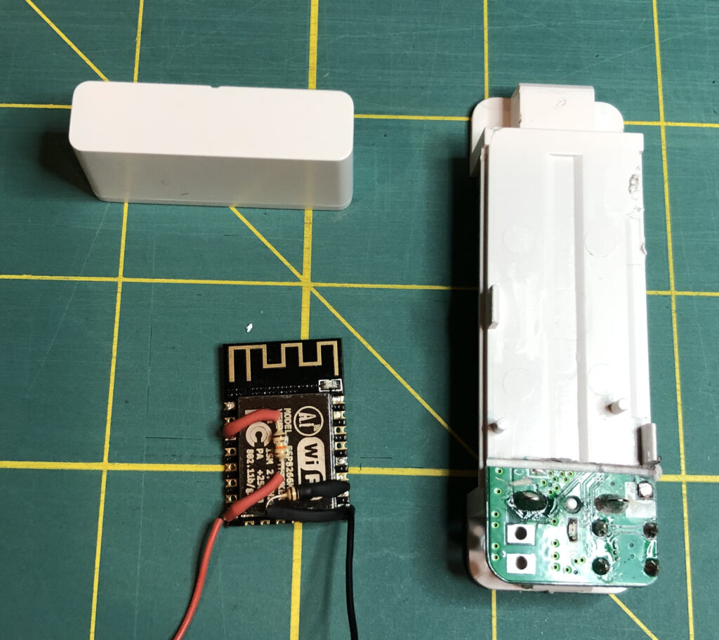
So I took to Ali to order some new reed switches (getting 10 this time!). Pay attention now – most reed switches are of the normally open type “NO”. This project needs a normally closed “NC” version. Searches will yield a version that has 2 leads coming out one side and are sold as both NO and NC. Fine. Just cut one lead once it’s all wired up. I also found some that appear to have a plastic casing (likely over the glass), but could not tell from the images. Anyway, since I didn’t need the original circuit, I cut away most of the board leaving the battery connector section.
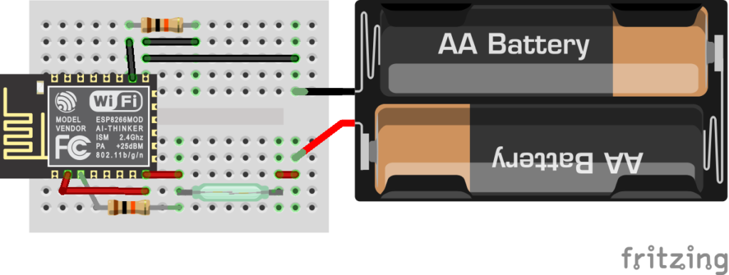
Here’s the bare minimum circuit to power up an ESP into boot mode (I know, it could probably use a CAP btw VCC and GND):
- GPIO 15 >> 10K >> GND
- EN (CH_PD) >> 10K >> VCC (3.3V in this case)
- GND >> Batt – and VCC >> Batt +
- VCC to A0 (for reading battery voltage)
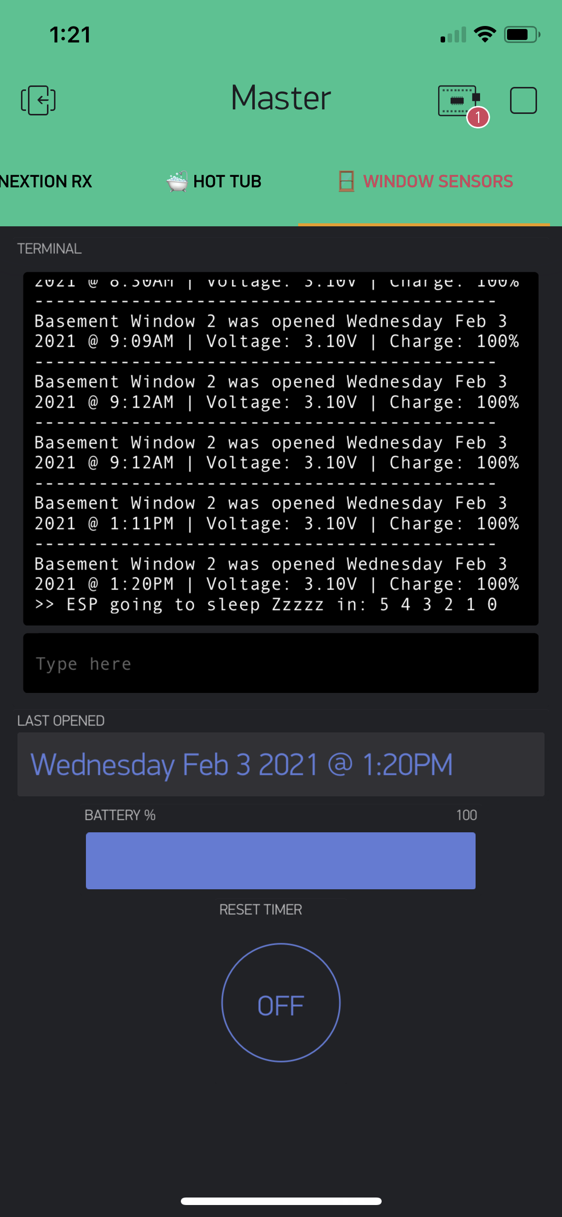
As noted, I use Blynk to integrate all my IoT projects. This is my master app that also controls/reports my WIoT-2 weather system. The Window Sensor tab uses a Terminal screen to report stats each time the window is open. Date, time, battery voltage, and when the ESP goes to sleep. It also get pop-up notifications. In the future, I will also have other Window sensors reporting into this as well.
Of course I don’t want to set off all sorts of alarms, and I plan to enhance the code to play around with the types of triggers. For example, using the terminal feature is silent and just updates the content. The Blynk.notify feature will trigger a notification with sound on the phone, so this would definitely raise attention in the middle of the night with the phone on my bedside table. I’ll also be looking at some IFTTT integration with my outdoor security cameras (e.g. to ensure they are recording etc).
Heads UP!
As I made this mistake myself, I’ll pass along a tip. The end state of this project is an ESP8266 with resistors soldered so it can boot when power is applied. Once this is done, you can’t really use the ESP programmer and need to rely on OTA for all future uploads. I had this working with OTA perfectly, but made a change that effectively bricked the unit (part of OTA), so I was SOL. Luckily I had more ESP modules laying around. So, before I decided to de-solder and re-program this one, I used another unit and the ESP programmer to continue coding/debugging. Once the code was solid I then replaced the bad one with the 2nd one. The good news is the ‘bad’ one wasn’t bad per-se, it just needed to be re-programmed on the programmer. For any significant code changes now, what I do is use a second unit and the ESP programmer to test the changes and verify they don’t brick OTA. Then, use OTA on the main unit and upload the new code.
Stats:
Key point before starting – when the window is closed, no power is being used. Zilch! Nada! Niente! Other that the batteries dyeing of their own parasitic drain, this sucker could last upwards of 19 years. Of course, this is not the case as there the window will be open for periods of time to get fresh air into the house, cleaning etc. However, since the ESP goes into deep sleep after 1 minute, there is still very little power drain.
Let’s break this down. Keep in mind the ESP goes into deep sleep after 1 minute of being powered up so leaving the window open for long periods of time will have very limited drain. I used my CurrentRanger to capture the following readings:
- 67 mA when the ESP is powered up for 1 minute using Wifi, talking to Blynk and waiting for an OTA connection.
- 12 uA (0.012mA) when in deep sleep.
- 2 x 1.5V AAA batteries. Conservative estimate of a total of 2000 mAh capacity.
Let’s assume the window is opened every day for 1 hour. This would work out as follows:
- 67mA over 1 minute = 6.7mA
- 0.012mA over 59 minutes >> 0.012 x 59 = 0.708mA
- Added we have 7.408mA over the hour consumed
- Math: 2000mAh /7.408 mA = 270 hours (note this does not account for other losses.)
- At one hour per day the batteries would last ~ 270 days give-or-take
It’s more likely the window would be open maybe 10 times / year, which works out to about 30 years… Batteries would corrode by then…
The Code:
Please see my Disclaimer page. A few things about the code:
- It integrates with Blynk for notifications. I highly recommend using this as your platform for IoT integration. Much of it is free and they have a low cost platform for using widgets. ..and no monthly costs!
- It uses the ESP8266 web-based OTA update process with enhancements I did to the web form.
- Battery % was calculated based on the min acceptable voltage for an ESP8266 to run which is 2.5V (considered 0%) and with 3.1V being 100%.
- Download the code below (zip file with .ino in it):
A lot of time goes into making and documenting these projects on my blog. Of course there are also costs involved. I use support funds toward future ideas, projects that I blog about here and share with others. Please consider supporting me at Ko-Fi below.
The Parts:
- axGear Smart WiFi Door Sensor. Try here or here. Note: I only ended up using this as a battery case as I used my own ESP8266 as well as a new reed switch. My next unit will be 3D printed. Keep in mind that you will need a magnet as well.
- ESP8266 12F Module
- ESP8266 Programmer
- Reed Switch here (make sure it’s Normally Closed)
- If you are going to build from scratch you will also need to 3D print the casing and get some small magnets
Here are some other interesting projects with similar intent:
- Mailbox Notifier based on a reed switch
What’s Next?
Now that I have a baseline unit, here are some initial thoughts on where I may take it next:
- Integrating with WIoT-2 to allow for notification icons to appear when a window has been left open (e.g. leaving the house).
- Looking into using IFTTT with my security cameras to ensure camera is recording scene. e.g. If window opens late at night, or overnight then trigger recording and notification (even though the camera may already do this itself).
- Now that I have baseline hardware, I’ll be looking at making this even smaller to run on 1-2 3V coin cells and a supercap (to handle current rush during WiFi comms). I figure I could get this down to half the size. I’ll also be modelling some designs to 3D print once I figure out what components I need.

Hello,
I am working on making a sensor like this but I am using Tasmota firmware . I do have it figured out turning papers off when window is closed by having the read switch looked up to power supply of my esp8266 but I am only able to tell when the window is open by when it connects online it send message to my MQTT broker. When the window is close it turns power off so it can’t send a message . What is a solution to solve this either waking it up when the window closed but has to send close message not another open message.
Not sure I entirely understand the question, but you could build a supercap into the project which would provide brief power on powerdown, then use this to send a ‘close’ message.