
Mazda Miata MX-5 Rear LED Strip Console Controller
Who wants one? Saddle over to this page for more info on how to get your hands on a flavour of this.
May 2022 Phase IV: Just finished what I hope to be the final iteration of this project. I’ve been searching for a wider colour IPS display and found one that will do (for now :-). Ideally, I’d like to fill the full area below in order to properly display the seatbeat and airbag warnings as well as status messages for the rear LEDs. I’m using a BuyDisplay 1.9 IPS display (320×170) mated to an ESP32 DEVKIT V1. As I had some challenges getting the display to work with the ESP using TFT_eSPI, I’ll probably do a video for that another time. Watch below to see the evolution of the build.
Feb 2022 Phase III: In my search for a better colour screen I swapped the black/white OLED for a colour IPS screen/controller using the TTGO T-Display ESP32 controller. However, this was a short-lived upgrade as it was not wide enough (per above), so I never made this permanent.
Phase II Build
If you are looking to build this project and don’t care much for the console controller, check out the Phase I build which focuses on the rear controller and LED strip. The below instructions are specific to using the black & white OLED and 2 controllers.
Backstory: Wanting to have more control of the Miata’s rear LED strip sequences and features (see my Phase I build), the next step was to build a controller into the center console unit that allows me to control them and also display state and status info. As I didn’t want to run wires through the car, the Master controller communicate wirelessly to the Slave unit. The details documented here builds on Phase I by adding the Master Control unit, and updating the Slave unit hardware to a NodeMCU ESP8266, and of course code updates for both as well.
Check out the video below for a demo of the features, then read on below for build details.
How it Works:
Both Master and Slave units use NodeMCU Mini ESP8266 MCUs and are setup to communicate to each other using Espressif’s ESP-NOW protocol. This saved the mess of having to run wiring through the car. The Master consists of the controller, a display, button and a few photoresistors. All of which are mounted into the front console unit. The Slave has the same MCU and an Adafruit NeoPixel LED strip with some other bits to monitor the brake signal. The Master unit allows scrolling through a number of different light sequences by way of the button. Short presses scroll the modes, a long-press initiates the selected mode.
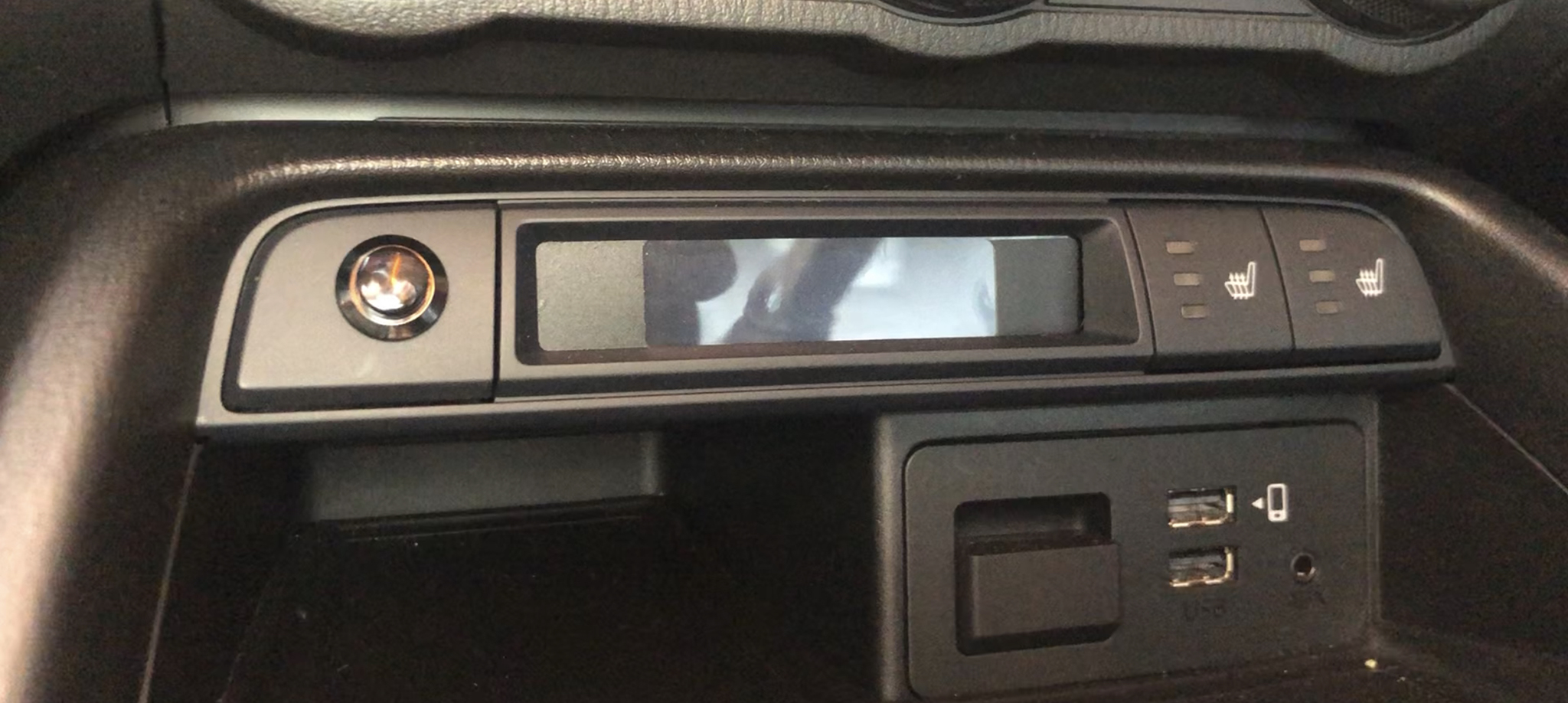
As the OLED covers up LEDs on the main console PCB board and status LEDs, I used a few photoresistors to “watch” both the Seatbelt and Airbag warning LEDs, and when they turned on, the OLED displays the relevant icon graphic. Yes, I’m aware of my blackout decal goof, but it can’t be seen at driving height angle 😉
Progress build pictures showing different parts of the console mods, fitting the OLED, controller, 3D printed case, etc.
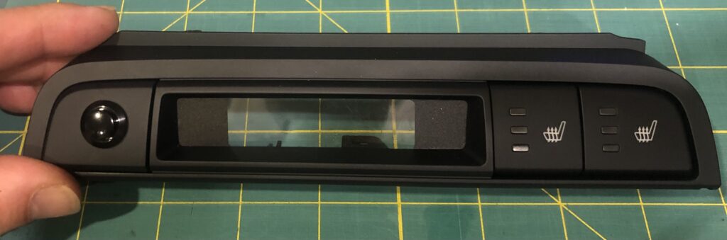
Console Modified Screen 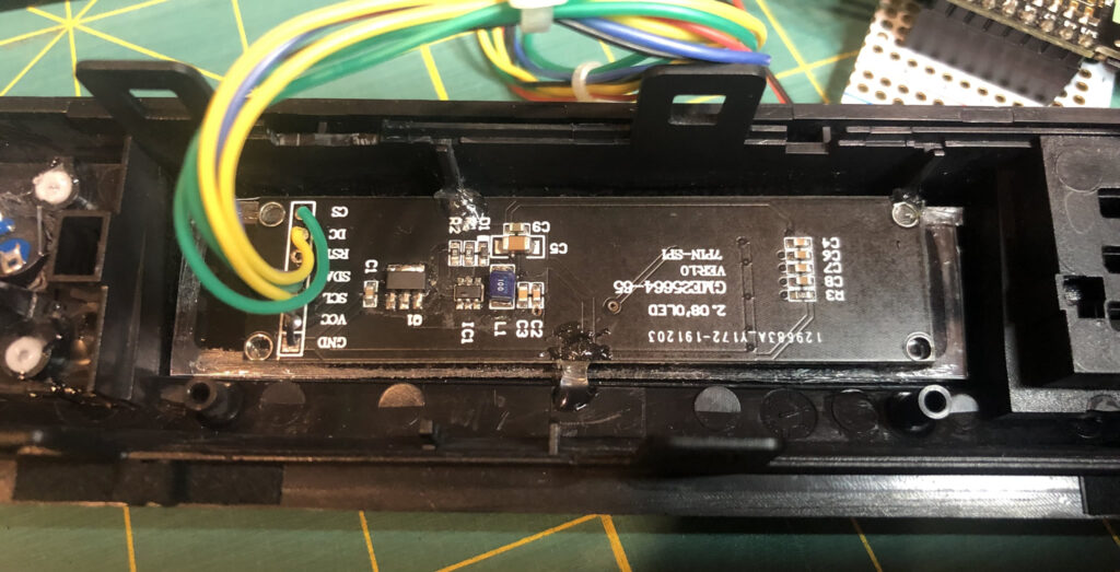
OLED Mounted 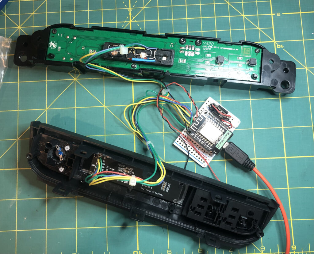
Console Unit 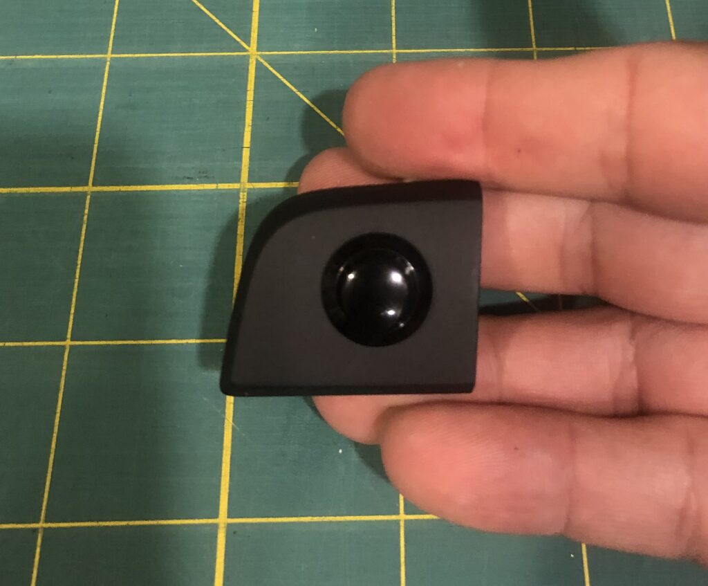
Push button for console 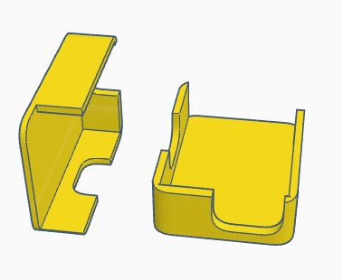
3D Template holder for ESP8266 Controller Unit 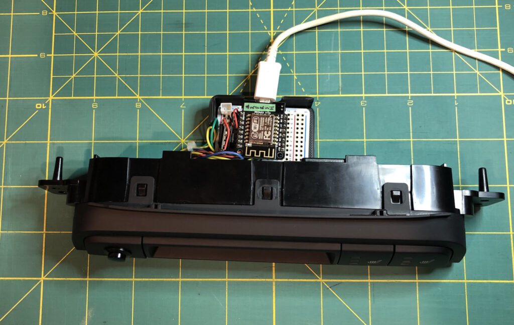
3D Template for Seatbelt/Airbag warning 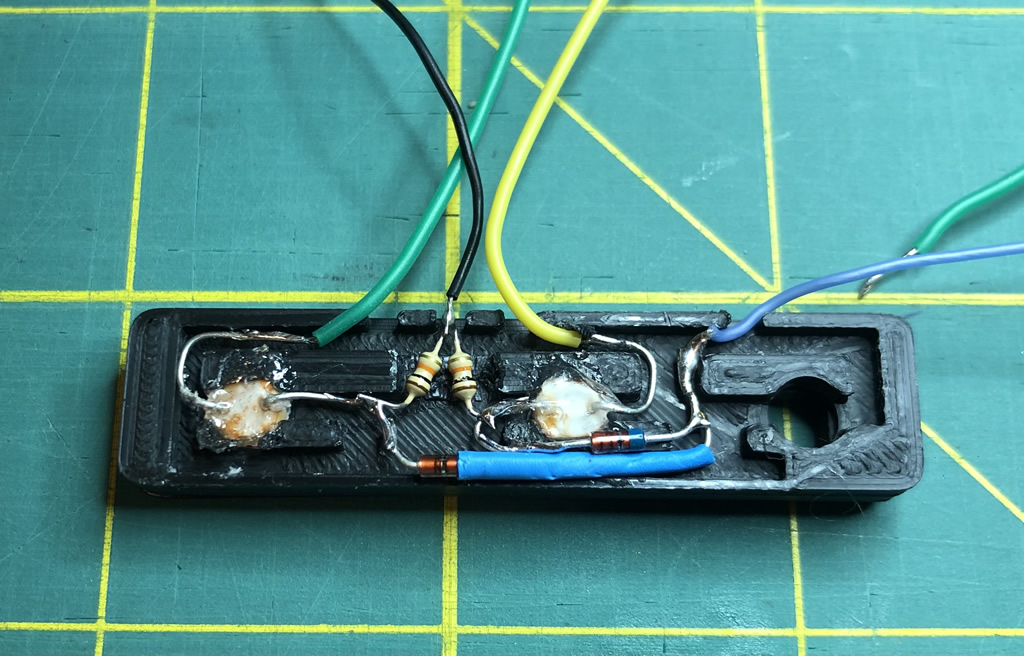
Photo Resistors Mounted 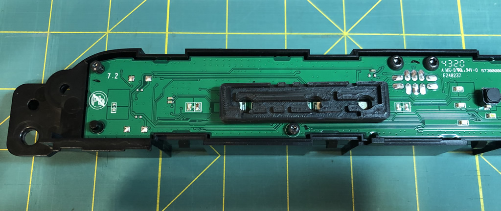
Light Channel 3D Print 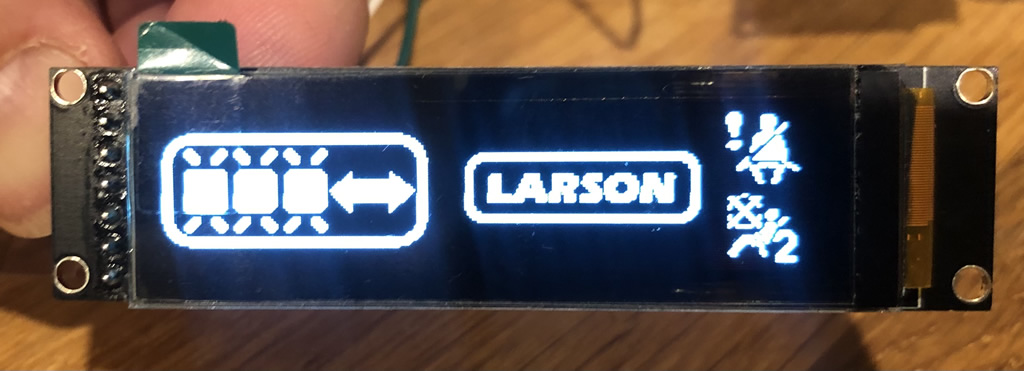
OLED Sample 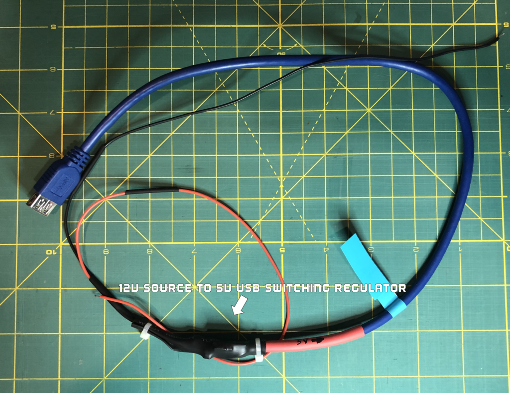
12V > 5V USB Wiring Harness 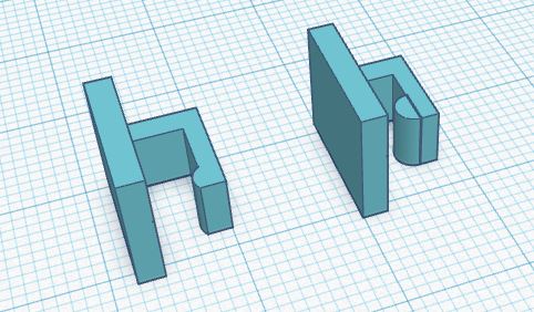
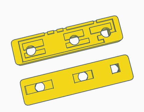
3D Printed Clips 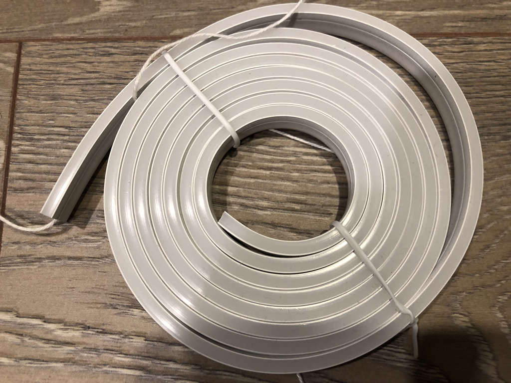
LED Light Pipe 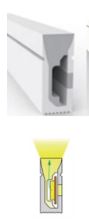
LED Light Pipe Light Direction 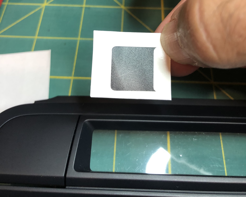
Blackout Decals
Demonstrating component testing and some early ideas before the final build:
The Build:
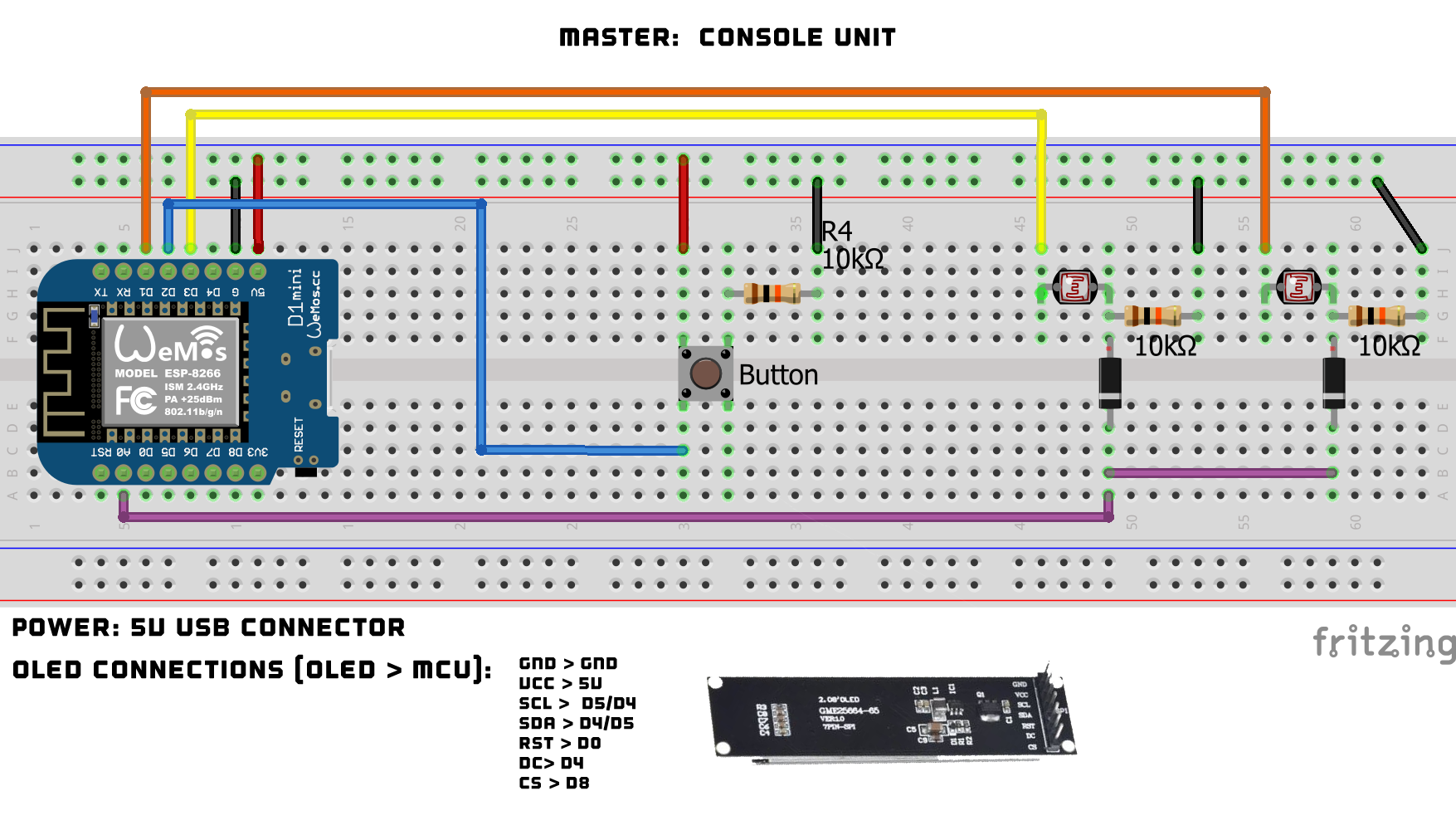
Master Unit: A little simpler, this consists of the NodeMCU Mini ESP8266, the OLED, and the photoresistors. For the OLED, I have to throw a ‘facepalm’ out there as I didn’t document the SCL/SDA pins – which also aren’t called out in the code (don’t need to). So, I basically forgot to note it after I hooked it all up and threw it in the car. I’ll update one day if I ever have to pull it out, but try using a combo of D5/D4 between the two to see which will work. Could also be D7/8 but D6 was not used. Sorry about that… For the sensing of the Seatbelt/Airbag alerts, I went a different route with the photoresistors due to there only being one Analog pin on this MCU. I’m using a multiplexing approach in the code. Basically each photoresistor is connected to a Digital pin which briefly powers up in alternating sequence, then through the resistor/diode combo the output is read via A0. The code does all this and reads the output of each effectively allowing 2 sensors on 1 (analog) pin. If you are using an MCU with > 1 Analog port, you can just break them out and read separately (also won’t need the diodes).
As for powering the master unit. I want to be able to upload code changes in the future. To do this, a USB cable is needed. Since USB also can provide power, and in the case of the master not much is needed, I just hacked up a USB cable in 2 parts. One cable is used to take 12V from the car Accessory fuse and drop it to 5V. The end of that cable is a USB female connector. Then I plug a standard USB cable from there into the NodeMCU. When I need to do code updates, I just unplug the USB cable, and plug into my tablet to update. The picture below shows the unit from fuse panel to USB female plug.
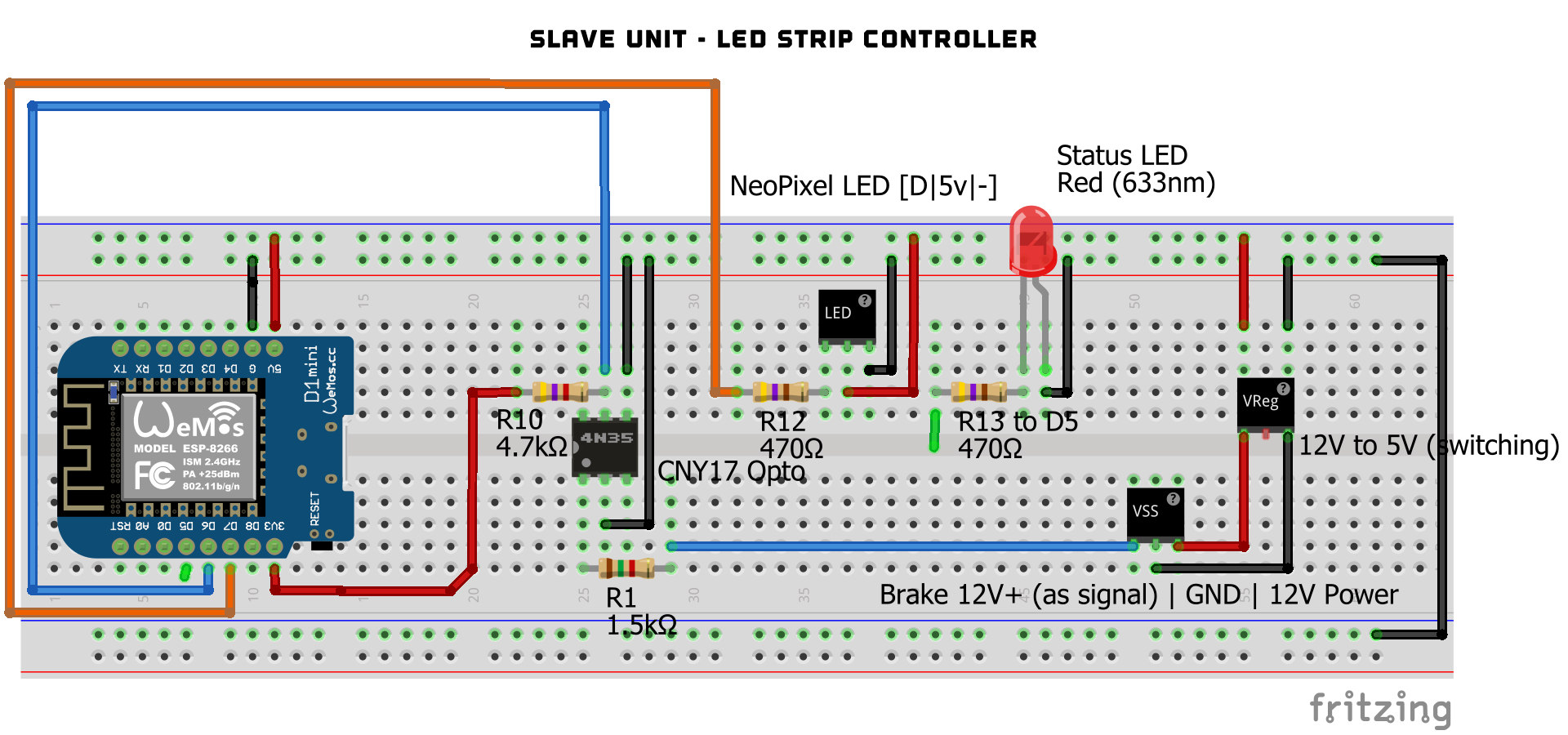
Slave Unit: The below schematic was updated from the Phase I build to include the NodeMCU Mini ESP8266 and remove the manual mode button. For specifics on that build, see the link above. The rest of the components are the same – the Opto to monitor the brakes, the LED strip connection, and switching voltage regulator. The Status LED is optional as it offers a way to monitor the Slave unit while mounted in the trunk. The code just sends a heartbeat blip to it.
Components:
| Master Unit | Slave Unit |
| NodeMCU Mini (you need 2) (5 pack here) | NodeMCU Mini (5 pack here) |
| OLED Display (AliExpress) | See Phase I build for other components |
| Pushbutton: This or these (12mm recommended) | LED Silicone Light Tube (optional). Varies depending on LED strip. For this project, T0410 was used (5mm wide LED strip). |
| OptoIsolator CNY17 | Custom 3D Printed clips to hold the light tube and wiring |
| Various resistors (10K) | |
| Power: Need to switch from 12V (vehicle) to 5V USB. I modified a USB cable with this in between. |
Your Support is Appreciated: A lot of time is put into developing my projects and the publishing of videos and these build logs. If you use them for your projects, please consider supporting me either via Ko-Fi or PayPal (below). It will go to purchasing new things for future projects and help support the work I do here. Thanks!
Future Thoughts:
I’m already thinking of new ideas. One thing that bugs me is the visibility of individual LED “pixels” when looking at the back of the car. I’m going to take a stab at using the below LED light channel. It has an semi-opaque side where the LEDs face which blends the light from each pixel, which makes the LEDs flow from one to another. I’m waiting on an order of another set of the LED strip which I’ll then install into this unit, do some testing and mount to the car.
..and done..

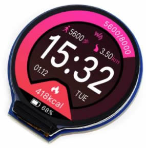
IPS Watch Display: Already thinking about this! The current OLED mono display was essentially the ONLY unit I could find that fit the console opening. It works, but the lack of colour and high resolution bugs me. I was initially searching for a colour IPS display in the same form factor, but after exhausting that, I don’t think they exist. Everything is too tall. I decided to think outside the box and consider these round watch displays. It won’t fit the console but I’ll look at 3D printing a casing of sorts and look for mounting options around the console area. Stay tuned for that!


I had saved this awhile back and the kind of forgot about it but it is really neat and I am thinking about it for my 2020 RF GT so you may get an order from me soon.