
Mazda MX-5 Miata: Funky NeoPixel LED Light Strip
Who wants one? Saddle over to my dedicated page for more info on how to get your hands on one of these kits.
It’s only been a few weeks since I’ve had my new 2021 Mazda Miata MX-5. Already added sequential LED turn signals & side markers all around, but not being the type to leave well enough alone, I needed a little spice to make it my own. Combining that with my passion of microcontrollers and LEDs ( see similar ) and taking inspiration from others before me (this) , here’s what I ended up with.
Update Oct 2021: Check out the latest version here! This project consists of 2 phases. Phase I (this page) is about the LED strip with standalone controller. It has 2 LED sequence modes that can be changed by a button on the controller (all inside the trunk or boot for our UK peeps!). Phase II (details here), takes it to the next level by adding Master controller / display in the front console that allows remote (wireless) control of the LED strip sequences. These pages provide info to build this version, or the whole enchilada!
How it Works:
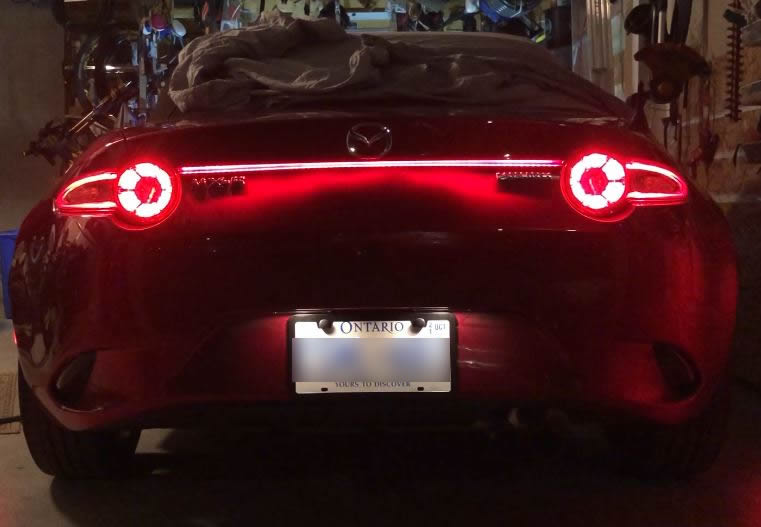
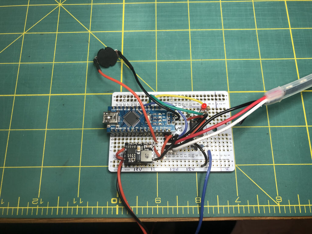
The heart is an Arduino Nano microcontroller with an Adafruit NeoPixel RGB LED light strip. The controller takes 12V power from the rear parking light, GND and 12V signal from the brake lights (when applied). When the car starts, parking gets power which fires up the controller/LEDs with a “bouncy” LED sequence intro on car start. For the rest of the time, the lights remain on as running lights while the controller monitors the brake signal. When brakes are applied, the LEDs sweep outwards in brake mode. The controller has a mode button so I can turn features (the “bouncy” bit) on/off (see future thoughts further down).
As this is a NeoPixel RGB LED colour strip each LED (90) can be individually controlled with millions of colours (and brightness control). In this case, I’m only using red and varying brightness. The entire system can all be tweaked via code using the Arduino Nano. This way I can change it up later if I get bored or get new ideas.
Technical Stuff:
- The system takes 12V DC and runs it through a switching regulator to drop the voltage to 5V – which is necessary for the Nano, NeoPixel strip and the OptoIsolator as they all use 5V. The Opto specifically uses 3v3 signal from the Nano.
- As I wanted to make sure this add-on would not drain the battery, it is only powered when the car starts/accessory is on (as note above – from the parking light power). I use the auto lighting feature, so it’s pretty much automated as well.
- The 12V brake signal runs through the 4N35 OptoIsolator which, when triggered, sends a signal (actually it’s HIGH by default and drops LOW when brakes are on) to the Nano on pin 3 (see code). The real purpose of an Opto is to separate high voltage from low. However, as GND is common across the system, it makes that somewhat moot! But, it does protect the Nano from voltage variation of a vehicle system (can range from ~11-15 Volts) by isolating those at the Opto itself. Something I don’t want to chance with a voltage divider as it assumes a specific voltage.
- When the vehicle is started the system can do one of 2 things depending on the mode button toggle. Default is that it goes into the K.I.T.T (Larson Scanner) & LED bounce sequence, then onto a normal “parking” light which triggers high (brighter) when braking. If the Mode button is toggled, it will bypass the K.I.T.T & bouncing LED sequences and go direct to parking/brake. When brakes are applied, the outer LEDs sweep out from center brightening in sequence, then go back to normal when brakes are not applied. A bit of Audi inspiration there.
Mounting and Installation:
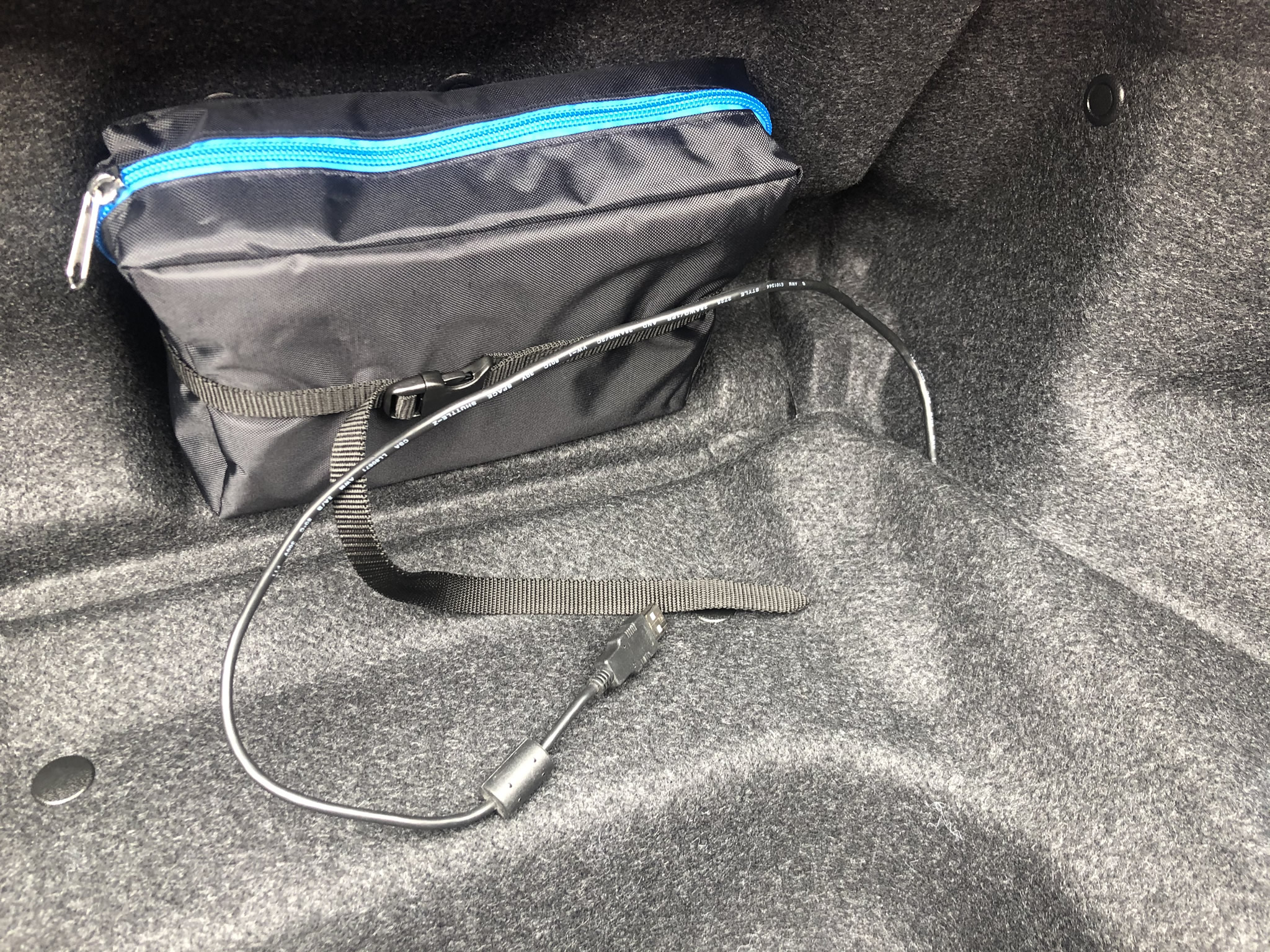
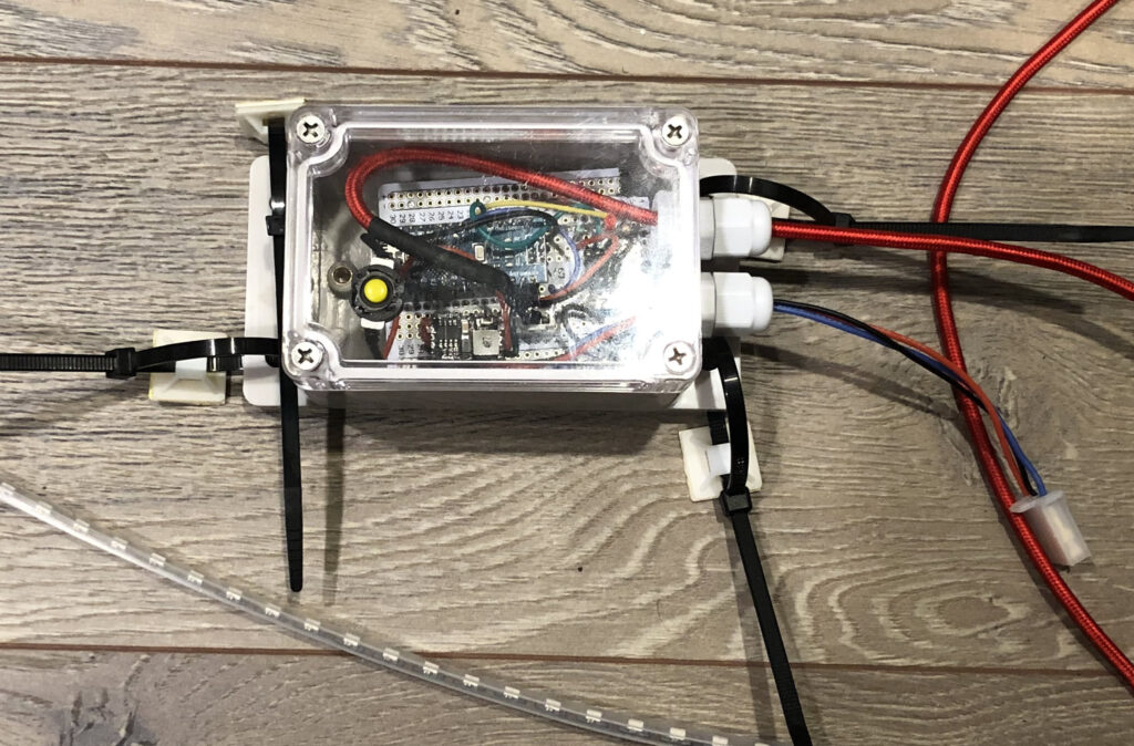
I decided to mount the LEDs under the trunk LID as I think it provides nicer lighting. To get the 12V, GND and 12V brake signal, I tapped into the extension cable that came with my sequential turn signal kit. You can also get something similar from mx5things. See pictures for controller box placement and cable runs. Those who have been there before can attest it’s nearly impossible to glue the LED strips cased in silicone. Instead, I custom modeled and 3D printed my own clips to fit this LED strip. Then added double-sided tape. I iterated a few times as my first design caused shadows by the clips close to LEDs. I came up with something that works by having the clip area set back (see pic) and not interfere the light cast pattern. Note these LEDs are side-facing (see pic below – light casts to the bottom). The top part of the clip stops ahead of that point, so no shadows!
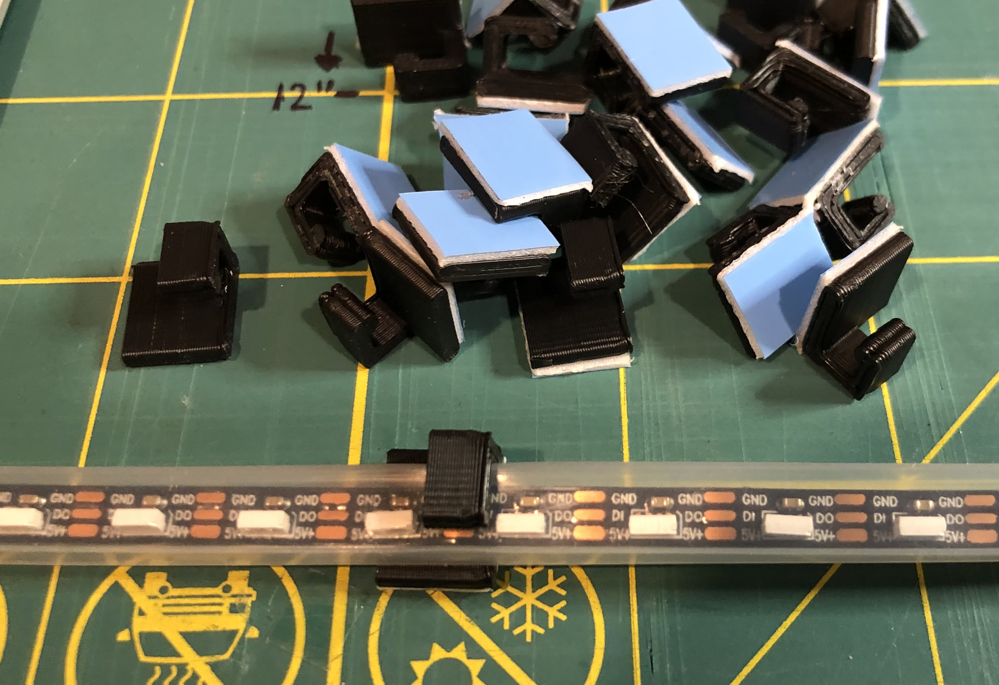

Mounting tabs 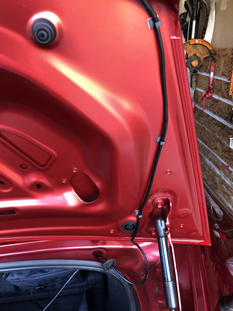
Cable run 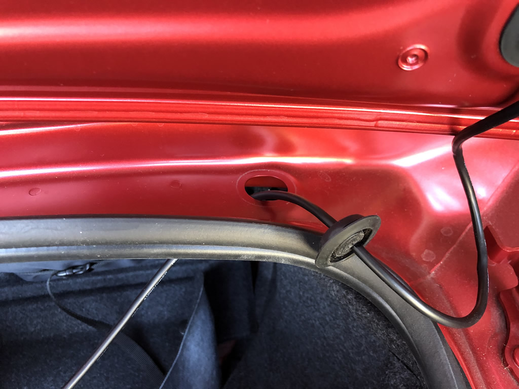
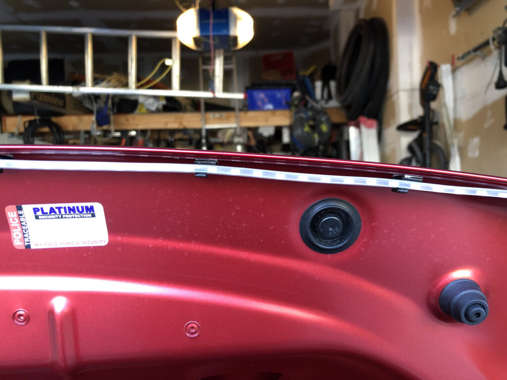
Grommet fitting 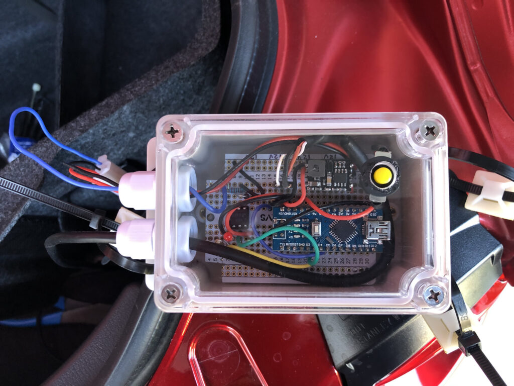
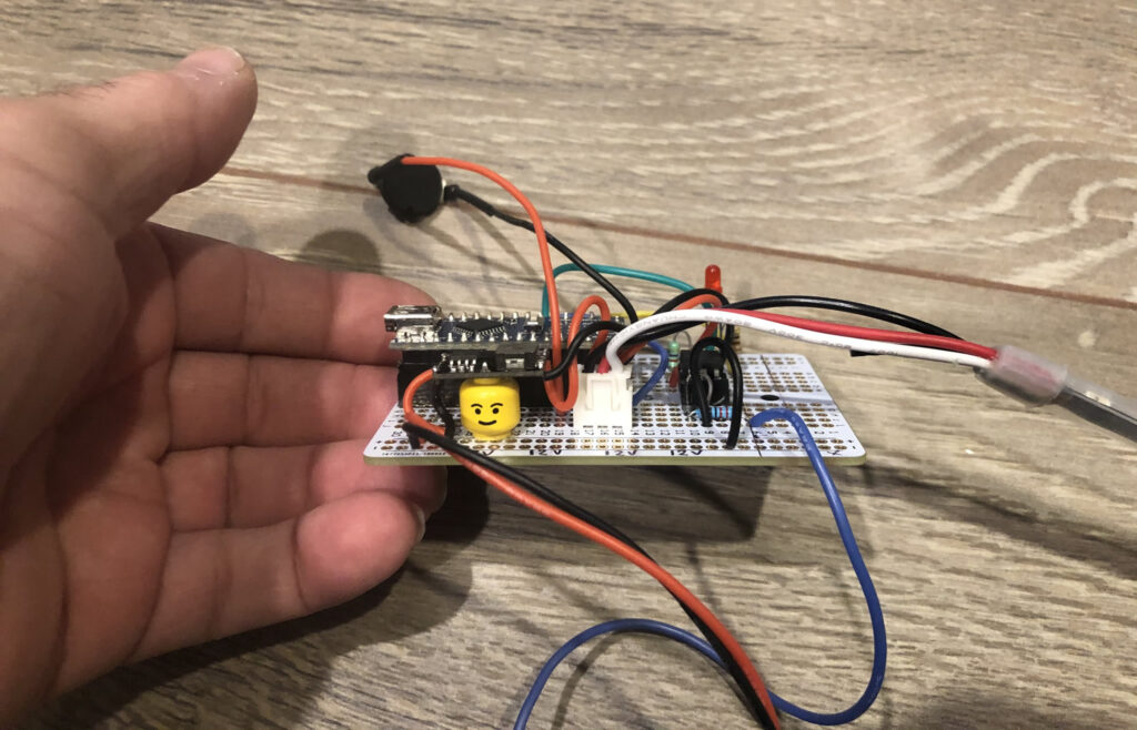
Getting controller ready to mount 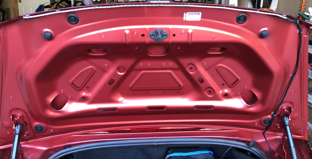
Strip mounted in trunk lip 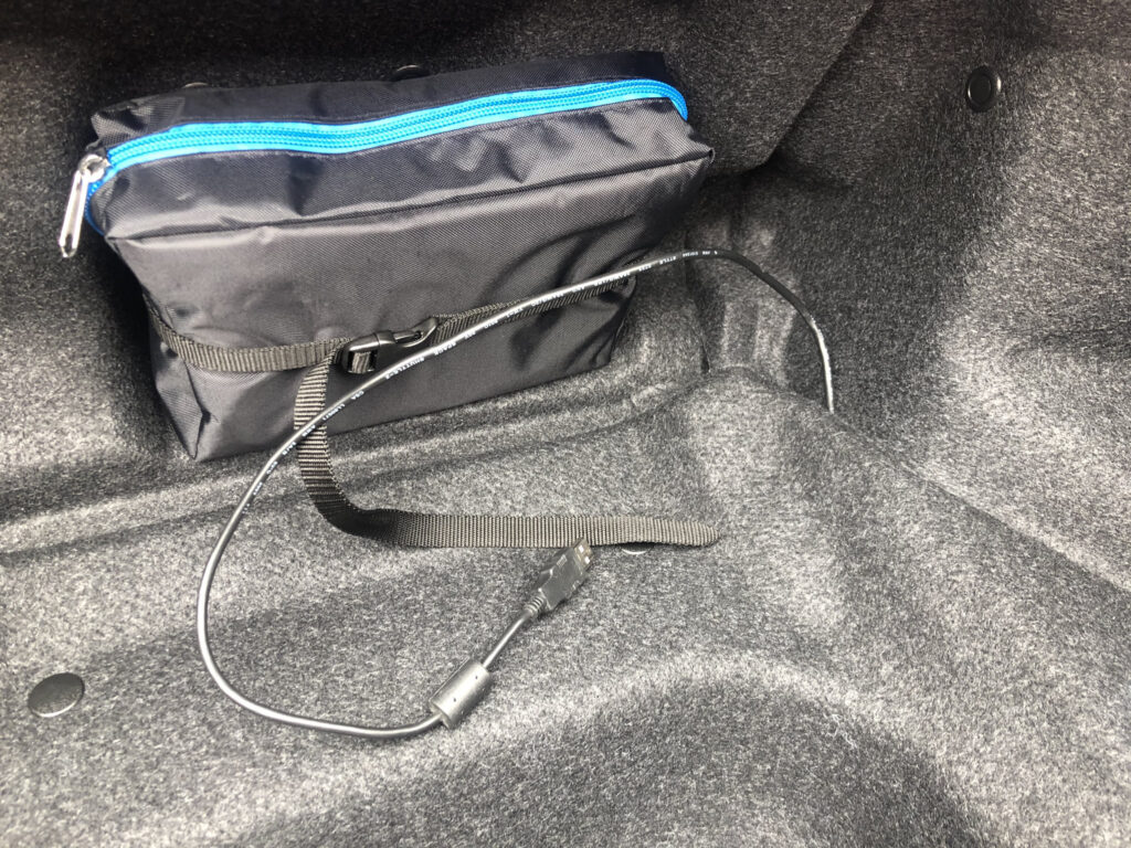
USB connection for re-programming
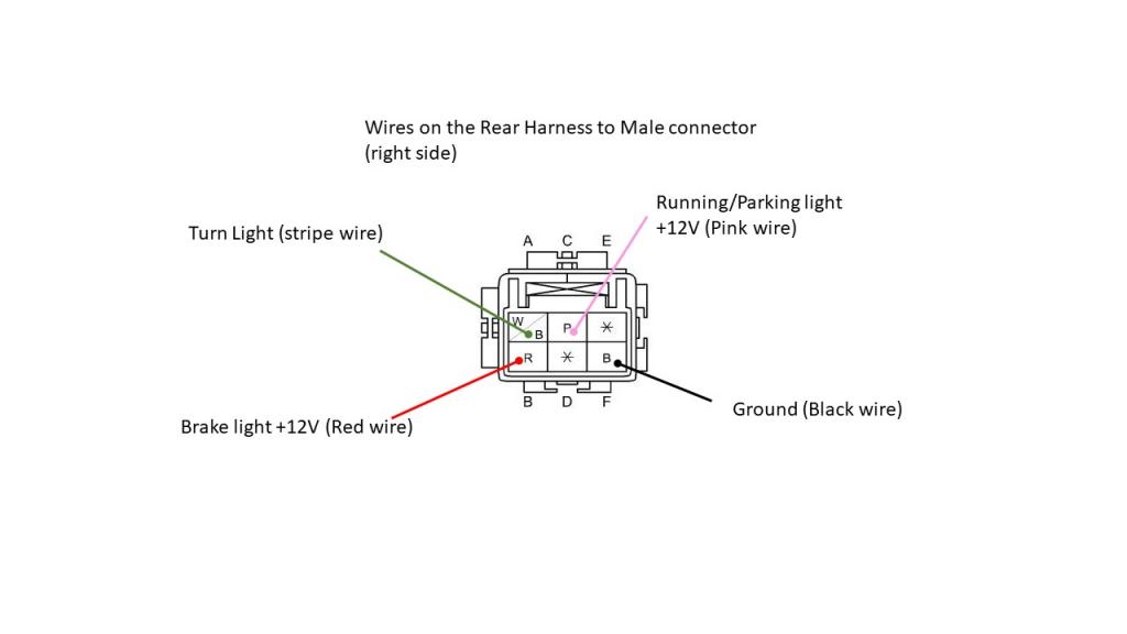
Rear Tail OEM Pins
Challenges:
In all this was a pretty straight forward build. However, I had a few challenges. I do most of my 3D printing with PLA-based material. Problem is things like double-sided tape don’t stick well to it. It holds, but over time slowly comes away – which is a bit of a problem as the LED strip will start to come loose. I think the tape I have is not the highest of quality, so will seek out some 3M. I’m going to try a few things and report back with updates. Upon finishing the project, I showed my wife and she laughed at the bouncy pattern, but the next words out of her mouth was “I want KITT, gotta have KITT… giggles”, so off I went and integrated a KITT feature. However, the challenge I now see is I expect I’ll want a few other modes/patterns. I will have to write the code, but it would be nice to be able to switch between them using my phone instead of re-programming each time. I want to do things on the fly (not while driving of course…) See the next section for more on that.
Future Enhancements:
Here are some ideas of future mods I’m thinking of doing:
- The current controller must be programmed directly via USB. In order to allow easy future tweaking I’ll probably switch to an ESP8266 and use Bluetooth to allow OTA (Over The Air) updates. This would also allow me to integrate with Blynk on my phone for changes on the fly such as mode switching, brightness and colour change tweaks etc.
- SuperCAP – I have been entertaining a power-down sequence that initiates when the car shuts down. I have to do some testing on this but the idea would be to have power loss detection (on the parking 12V VSS pin) that would trigger a sequence in code. That is assuming I can determine what power/duration of juice is needed from the supercap. I have a few laying around that I’ll test out and update at a later time.


Please sell me the brains wired up.
Ill print stuff and make a project box.
I can solder and fix anything needed.
I sent you a message on miata.net – point is i wanna buy one. 🙂
I am very interested in this Dynamic LED…. will you sell it??
At this point, I’m not looking at building and selling these as the cost would likely be too high for most to want to pay.